Motion controller Features

R64MTCPU/R32MTCPU/R16MTCPU
- Concept
- Features
- CPU Buffer Memory
- Motion SFC
- SSCNETIII/H
- Positioning Control
- Advanced Synchronous Control
- Advanced Pressure Control
- Multi-axis Adjustment Function
- Servo System Recorder
- G-code Control
- Machine Control Function
- Optical Hub Unit
- Functions List
- Related Link
Concept
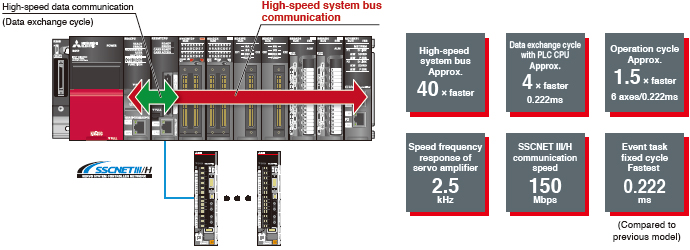
The MELSEC iQ-R series is provided with sophisticated dual engines: the PLC CPU engine for machine control and the Motion CPU engine for Motion control. The engines respectively process different types of control based on the characteristic of each engine while working together on data through a high-speed system bus. CPU loads are significantly distributed by these dual engines compared with a single engine, enabling any equipment to maximize its performance, even for a load change machine or multi-axis equipment.
The MELSERVO-J4 series servo amplifier is an environmentally and user friendly product, while offering industry-leading level of performance. Connecting the amplifiers to "SSCNETIII/H" optical network enables high-speed and high-accuracy control with the MR-J4 dedicated engine and high-resolution encoder.
Select the most suitable combination of CPU engines that can reduce cost and maximize machine performance to the fullest from our extensive product line. Efficiency in designing and debugging is also improved.
Programming efficiency matters when it comes to productivity. The MELSEC iQ-R series optimizes all procedures, from designing, debugging, to startup.
Equipped with advanced dual engines that are only possible with our cutting-edge iQ platform technology, the MELSEC iQ-R series takes a step further to accelerate the equipment revolution by collaborating with our partner companies. Now, a wide variety of partner products are available, such as stepping motors and direct drive motors.
Features
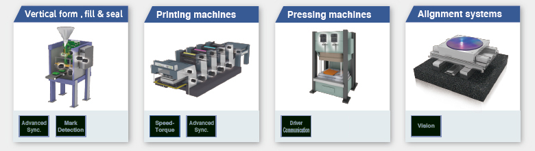
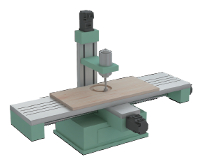
- The MELSEC iQ-R series Motion controller is capable of various controls such as positioning control, speed control, torque control, tightening & press-fit control, advanced synchronous control and cam control, etc. They are applied to various machines such as X-Y tables, unwinding machines, packing machines and filling machines.
- A combination of Mitsubishi's advanced PLC system, servo amplifiers, servo motors, and servo networks offers exceptional solutions that allow you to maximize your system's productivity.
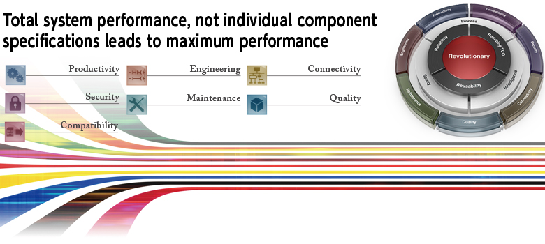
Higher Basic Performance and Further Improved Total System Performance
Experience Powerful Performance of Multiple CPU with Ease of Use Just Like Using One CPU
You can select either the Motion CPU or the PLC CPU based on the application, allowing you to configure a system more flexibly.
The easy-to-understand flowchart form is adopted by Motion SFC for Motion control programming.
Also, the direct positioning start instruction allows you to program Motion control, such as positioning and synchronous controls, just with sequence programs.
Motion CPU Memory Expansion
- The cam working area has been expanded to 16M bytes, enabling you to use more cam data with higher resolution.
- The device memory has been increased to 128k words, so even multi-axis equipment requiring more devices can be applied.
- The cam data storage area has been expanded to 12M bytes. SD card is also available for storing cam data.
Ease of Use Achieved by a State-of-art CPU Buffer Memory
The high-speed, high-capacity CPU buffer memory revolutionizes the data exchange between CPUs.
The PLC CPU and the Motion CPU each have a CPU buffer memory. And those buffer memories are efficiently utilized for two different purposes.
- The 2M words CPU buffer memory (Motion CPU side) is provided as standard, which is utilized for bulky data transmission and fast data updating.
- The CPU buffer memory (fixed-cycle communication area) allows 24 k words (4 CPUs in total) transmission between the PLC CPU and the Motion CPU every 0.222 ms. It is perfectly suited for receiving/transmitting highly synchronized data between multiple CPUs.
CPU Buffer Memory
The Motion CPU and the PLC CPU are equipped with 2 M words and 512 k words CPU buffer memories respectively.
They allow for bulky data transmission and fast data update.
Bulky data such as cam data can be transferred by just a one-time transmission through the 512 k word buffer memory.
The data that is set on Motion CPU side can be reflected to the interlock in the sequence program without any delay.
CPU Buffer Memory (Fixed-cycle Communication Area)
Data can be transmitted every 0.222 ms between the PLC CPU and the Motion CPU. The CPU buffer memories (fixed-cycle communication area) are synchronized to the Motion control, optimizing the operation.
Motion SFC Program
The Motion control program is described in flowchart form using the Motion SFC (Sequential Function Chart) format.
The Motion SFC format program is suitable for event processing and allows the Motion CPU to perform batch control of multiple sequential machine operations, pursuing high event responsiveness.
Flowchart description is easy to
read and understand
- The machine operation procedure is visualized in the program by using the flowchart descriptions.
- A process control program can be created easily, and control details can be visualized.
Controlling sequential machine operation using
the Motion CPU
- Servo control, I/O control, and operation commands can be combined in the Motion SFC program.
- Motion SFC program can execute servo control by itself, eliminating the need of creating the sequence program for servo control.
High-speed Synchronous Network SSCNETIII/H
- Communications speed is increased to 150 Mbps full duplex (equivalent to 300 Mbps half duplex), three times faster than the conventional speed.
System response is dramatically improved. - Smooth control of a machine is possible using high-speed serial communications with a cycle time of 0.222 ms.
- Synchronous communications are achieved with SSCNETIII/H, offering technical advantages for machines that require deterministic control.
- Long distance wiring is possible up to 3200 m (10498.69 ft.) per system (maximum of 100 m (328.08 ft.) between stations x control axes up to 32 axes), suitable for large-scale systems.
- SSCNETIII/H compatible and SSCNETIII compatible servo amplifiers can be used together.
(The communications speed when SSCNETIII compatible products are used together in the same system: 150 Mbps full duplex)
(Note): SSCNET (Servo System Controller Network)
Positioning Control
A variety of positioning controls, such as PTP control, position follow-up, and continuous path control are available with the Motion controller.
Basic Positioning Control
- To respond to various applications, the Motion controller offers various control methods such as PTP control, speed control, speed-position switching control, continuous path control, position follow-up control, Speed control with fixed position stop, and high-speed oscillation control, etc.
- Powerful auxiliary functions are available such as M-codes, the target position change function, the acceleration/deceleration time change function, and the advanced S-curve acceleration/deceleration.
- Positioning operation can be activated by Motion SFC, or the direct positioning start instruction by the PLC CPU, etc.
Advanced Synchronous Control
The advanced synchronous control is software-based synchronous control as an alternative to mechanical control, such as gear, shaft, clutch, speed change gear and cam. In addition, cam control becomes even easier with cam auto-generation function.
- The synchronous control can be started/ended on axis-by-axis basis.
- Axes in synchronous and positioning controls can be used together in one program.
- Speed-torque control can be performed simultaneously with the synchronous control.
- Up to 192 axes can be synchronized by use of three R64MTCPU modules.
All axes are synchronized using a synchronous encoder axis or a servo input axis.
Application examples- Packing machines
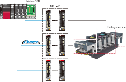
- Printing machines
- Diaper manufacturing machines
- Tire molder
Only two axes are in synchronization. Axis 2 is set as to synchronize to axis 1. The other axes are in positioning control.
Application examples- Tandem configuration
Multiple CPU advanced synchronous control
A large system can be configured thanks to the advanced synchronous control that allows up to 192-axis synchronization with high accuracy by use of three R64MTCPUs.
Synchronous Control Parameters
- The synchronous control is easily executed just by setting parameters.
- One of the following three can be set as the input axis: Synchronous encoder axis, Command generation axis, or Servo input axis.
- "Command generation axis" is not counted as a control axis; therefore all the control axes can be used as output axes.
- The cam axis can be operated in linear operation (a rotary table, a ball screw, etc.), two-way operation, or feed operation by setting cam No. and cam data.
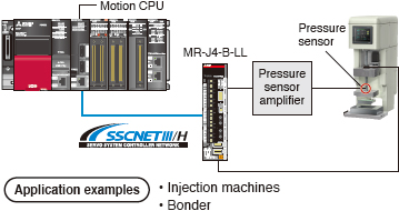
Advanced Pressure Control
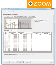
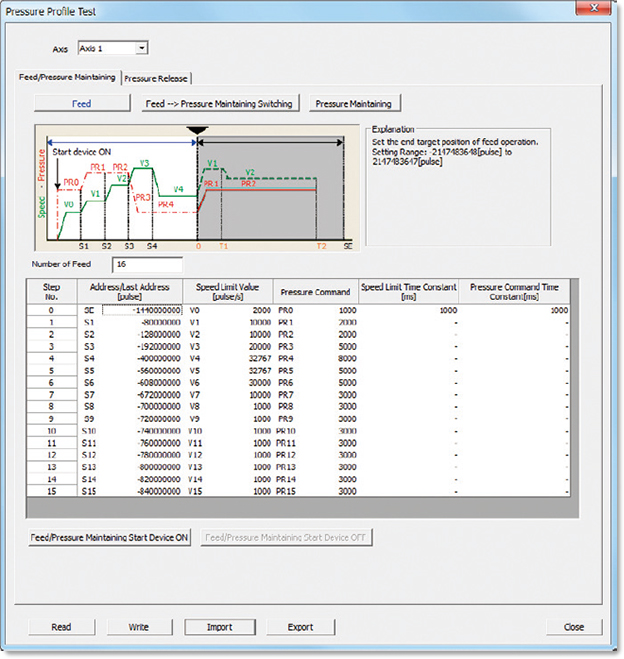
The machine is controlled so that the pressure commands match the pressure sensor values; therefore pressure is maintained constant even with a changing load. Each pressure process ("Feed", "Pressure maintaining", and "Pressure release") can be set with the Pressure Profile, and those processes can be tested on MELSOFT MT Works2, which makes a changeover and adjustment easy.
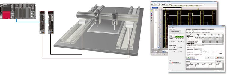
Multi-axis Adjustment Function
The multi-axis adjustment function enables simpler servo adjustment and quicker startup for machines executing multi-axis simultaneous operation, such as a tandem configuration.
- Multi-axis simultaneous JOG operation by specifying speed and acceleration/deceleration time
- Multi-axis simultaneous positioning
- Multi-axis simultaneous tuning by the same settings
Servo System Recorder
The Motion module automatically collects data of all servo amplifiers when an error occurs. The collected data, such as the command and the feedback values, greatly helps you analyze the error cause.
- Automatic collection of data, such as position, speed, and torque data, without programming.
- Data collection of all axes, which helps you locate the error cause even when the error is caused by the other axes without an error.
- The co-recording function collects data even when an error occurs in other recording devices.
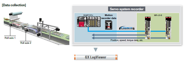
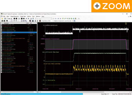
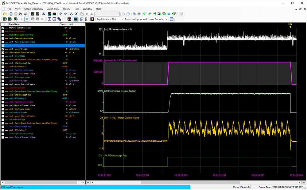
GX LogViewer
The collected data can be checked on GX LogViewer.
The operation status before and after an error is displayed in waveform, which allows you to analyze more operation details and helps you locate the error cause.
[Features]
- Displays the collected data and events graphically.
- Enables users to adjust a graph easily by automatic adjustment function and drag operation.
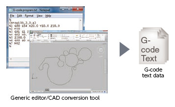
G-code Control

G-code control is available by additionally installing the G-code control add-on library (additional charge).
G-code control is applied to various types of path control such as drawing and cutting by a simple machine tool.
- Up to 16 axes can perform G-code control (Simultaneous interpolation: Up to 4 axes).
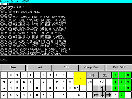
- A G-code program, which is in text format, can be edited with a generic editor.
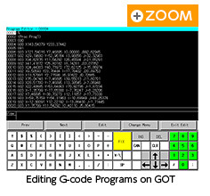
- G-code programs can be edited and read from/written to a Motion controller with GOT2000.
Machine Control Function
The Motion controller controls a simple industrial robot by installing an add-on library "Machine Library".
The robot is controlled by machine control with Cartesian space coordinates.
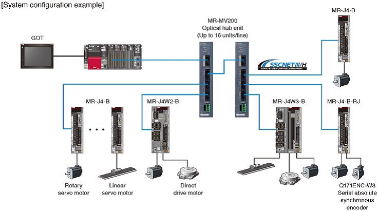
Optical Hub Unit
The MR-MV200 optical hub unit can branch a single SSCNETIII/H network line in three separate directions. This enables distribution of the SSCNETIII/H compatible devices with flexible wiring arrangement. In addition, the distributed amplifier can be partly OFF for maintenance without stopping the whole system; thus, the machine availability can be improved.
- The SSCNET connect/disconnect function of the controller allows you to power off only the desired servo amplifiers.
- The optical hub unit is introduced just by making some changes in wiring without making any new settings.
- Longer-distance wiring becomes available by using the optical hub unit.
- (Note):
- Be sure to confirm that "SSCNETIII/H" is selected in the system setting when introducing the optical hub unit.
Functions List
| Motion controller | ||||
|---|---|---|---|---|
| R64MTCPU | R32MTCPU | R16MTCPU | ||
| Number of control axes | Up to 64 axes (32 axes/line x 2) | Up to 32 axes (16 axes/line x 2) | Up to 16 axes | |
| Servo amplifier interface | SSCNETIII/H (150 Mbps) | |||
| Maximum distance between stations [m(ft.)] |
100 (328.08) | |||
| Connectable servo amplifier | MR-J5-B, MR-J5W-B More details MR-J4-B, MR-J4W-B More details MR-JE-B More details |
|||
| Operation cycle[ms] (Operation cycle settings) |
From 0.222ms | |||
| Engineering Environment | MELSOFT MT Works2 | |||
| Programming method | Motion SFC, Direct positioning start instruction | |||
| Control modes | Position control, Speed control, Torque control, Tightening & press-fit control, Synchronous control, Cam control, Advanced synchronous control, G-code control, Machine control |
|||
| Positioning control | PLinear interpolationm, Circular interpolation, Continuous path control, Helical interpolation, Position follow-up control, Speed control with fixed position stop, High-speed oscillation control, Speed/position switching control |
|||
| Acceleration/deceleration process | Trapezoidal acceleration/deceleration, S-curve acceleration/deceleration, Advanced S-curve acceleration/deceleration |
|||
| Manual control | JOG operation, Manual pulse generator, JOG operation simultaneous start | |||
| Functions that change control details |
Current value change, Target position change, Torque limit value change, Speed change | |||
| Home position return method | Proximity dog method 1, Proximity dog method 2, Scale home position signal detection method, Count method 1, Count method 2, Count method 3, Data set method 1, Data set method 2, Dog cradle method, Stopper method 1, Stopper method 2, Limit switch combined method, Dogless home position signal reference method |
|||
| Auxiliary functions | Forced stop method, Hardware stroke limit method, Software stroke limit method, Absolute position system, Amplifier-less operation method, Unlimited length feed method, Optional data monitor method, Mark detection method, M-code output method, Error history, Digital oscilloscope method, Vision system connection function, Security function, Limit switch output method,Cam auto-generation method, Driver Communication, Servo system recorder, Command generation axis, Vibration Suppression Command Filter |
|||
| 5VDC internal current consumption [A] |
1.20 | |||
| Mass [kg] | 0.28 | |||