Earth-Leakage Relays

Earth-Leakage Relays
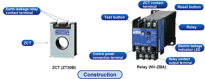
- Unlike on an earth leakage breaker, there is no interruption performed and there is only an earth leakage detection function.
Detection of the earth leakage is performed (ZCT) and then a signal is sent when there is earth leakage (relay part).
It is used with a combination of a ZCT (zero-phase current transformer) and a relay.
Lineup
| Model | Interchangeable leakage relays (*1) | |||||||||||||||||||||||||||||||||||||||
|---|---|---|---|---|---|---|---|---|---|---|---|---|---|---|---|---|---|---|---|---|---|---|---|---|---|---|---|---|---|---|---|---|---|---|---|---|---|---|---|---|
| Electrical self-hold type | Mechanical self-hold type | |||||||||||||||||||||||||||||||||||||||
| Hole diameter (mm) | NV-ZBA | NV-ZSA | ||||||||||||||||||||||||||||||||||||||
| Model of ZCT (*5) |
15 | ZT15B | - | ZT15B | - | |||||||||||||||||||||||||||||||||||
| 30 | ZT30B | - | ZT30B | - | ||||||||||||||||||||||||||||||||||||
| 40 | ZT40B | - | ZT40B | - | ||||||||||||||||||||||||||||||||||||
| 60 | - | ZT60B | - | ZT60B | ||||||||||||||||||||||||||||||||||||
| 80 | - | ZT80B | - | ZT80B | ||||||||||||||||||||||||||||||||||||
| 100 | - | ZT100B | - | ZT100B | ||||||||||||||||||||||||||||||||||||
| Image |  |
 |
||||||||||||||||||||||||||||||||||||||
 |
|
|||||||||||||||||||||||||||||||||||||||
| Wiring system | 3φ4W, 3φ3W, 1φ3W, 1φ2W | |||||||||||||||||||||||||||||||||||||||
| Control voltage AC (V) |
JIS | 100・200 selectable | 100・200 selectable 200・415 selectable |
|||||||||||||||||||||||||||||||||||||
| UL/JIS(*2) UL/CE(*3) |
- | - | ||||||||||||||||||||||||||||||||||||||
| JIS | High speed type |
Rated sensitivity current (mA) | 30 100・200 ・500 selectable |
100・200 500 selectable |
30 100・200 ・500 selectable |
100・200 500 selectable |
||||||||||||||||||||||||||||||||||
| Max. operating time (s) | 0.1 | 0.1 | ||||||||||||||||||||||||||||||||||||||
| Delay type |
Rated sensitivity current (mA) | 100・200・500 selectable | 100・200・500 selectable (200・500・1000 selectable) |
|||||||||||||||||||||||||||||||||||||
| Operating time (s)(*4) | 0.3・0.8 ・1.6 selectable |
0.3・0.8 ・1.6 selectable |
||||||||||||||||||||||||||||||||||||||
| Inertial non-operating time (s) or longer than (s) | 0.1・0.5・1.1 | 0.1・0.5・1.1 | ||||||||||||||||||||||||||||||||||||||
| UL/JIS | High speed type |
Rated sensitivity current (mA) | - | - | ||||||||||||||||||||||||||||||||||||
| Max. operating time (s) | ||||||||||||||||||||||||||||||||||||||||
| Delay type |
Rated sensitivity current (mA) | |||||||||||||||||||||||||||||||||||||||
| Max. operating time (s)(*4) | ||||||||||||||||||||||||||||||||||||||||
| Inertial non-operating time (s) or longer than (s) | ||||||||||||||||||||||||||||||||||||||||
| UL/CE | High speed type |
Rated sensitivity current (mA) | - | - | ||||||||||||||||||||||||||||||||||||
| Max. operating time (s) at 5IΔn | ||||||||||||||||||||||||||||||||||||||||
| Delay type |
Rated sensitivity current (mA) | |||||||||||||||||||||||||||||||||||||||
| Max. operating time (s) at 5IΔn (*4) | ||||||||||||||||||||||||||||||||||||||||
| Inertial non-operating time (s) at 5IΔn | ||||||||||||||||||||||||||||||||||||||||
| Earth leakage indication | Electric type (LED) | Mechanical type (button) | ||||||||||||||||||||||||||||||||||||||
| Resetting method | Push button or control power switch off |
Push button (combined with earth leakage indicator) |
||||||||||||||||||||||||||||||||||||||
| Built-in contact | Configuration | 1c | 1a1c | |||||||||||||||||||||||||||||||||||||
| Continuous current capacity (A) |
5 | 5 | ||||||||||||||||||||||||||||||||||||||
| Contact capacity (A) |
|
|
||||||||||||||||||||||||||||||||||||||
| Connection | Front | ●Clamp terminal | ●Clamp terminal | |||||||||||||||||||||||||||||||||||||
| Rear | - | ●Clamp terminal | ||||||||||||||||||||||||||||||||||||||
| Mass (kg) | Relay | 0.3 | 0.4 | |||||||||||||||||||||||||||||||||||||
| External accessories | Terminal cover | ●(TC-ZBA) | ●(TC-ZSA) | |||||||||||||||||||||||||||||||||||||
| Mounting hook for IEC 35mm rail (DIN rail) Fixture | ●(DIN-ZBA) | - | ||||||||||||||||||||||||||||||||||||||
| Max. consumption (VA) | 3 | |||||||||||||||||||||||||||||||||||||||
| Conforming standard | US UL standard (UR certified) |
- | - | |||||||||||||||||||||||||||||||||||||
| European CE marking | - | - | ||||||||||||||||||||||||||||||||||||||
| Model | Interchangeable leakage relays (*1) | |||||||||||||||||||||||||||||||||
|---|---|---|---|---|---|---|---|---|---|---|---|---|---|---|---|---|---|---|---|---|---|---|---|---|---|---|---|---|---|---|---|---|---|---|
| Harmonic surge ready | Harmonic surge ready | |||||||||||||||||||||||||||||||||
| Electrical self-hold type | Mechanical self-hold type | |||||||||||||||||||||||||||||||||
| Hole diameter (mm) | NV-ZHA | NV-ZLA | ||||||||||||||||||||||||||||||||
| Model of ZCT (*5) |
15 | ZT15B | ZT15B | |||||||||||||||||||||||||||||||
| 30 | ZT30B | ZT30B | ||||||||||||||||||||||||||||||||
| 40 | ZT40B | ZT40B | ||||||||||||||||||||||||||||||||
| 60 | ZT60B | ZT60B | ||||||||||||||||||||||||||||||||
| 80 | ZT80B | ZT80B | ||||||||||||||||||||||||||||||||
| 100 | ZT100B | ZT100B | ||||||||||||||||||||||||||||||||
| Image |  |
 |
||||||||||||||||||||||||||||||||
|
|
|||||||||||||||||||||||||||||||||
| Wiring system | 3φ4W, 3φ3W, 1φ3W, 1φ2W | |||||||||||||||||||||||||||||||||
| Control voltage AC (V) |
JIS | - | - | |||||||||||||||||||||||||||||||
| UL/JIS(*2) UL/CE(*3) |
120・240 selectable 240・440 selectable |
120・240 selectable 240・440 selectable 480 |
||||||||||||||||||||||||||||||||
| JIS | High speed type |
Rated sensitivity current (mA) | - | - | ||||||||||||||||||||||||||||||
| Max. operating time (s) | ||||||||||||||||||||||||||||||||||
| Delay type |
Rated sensitivity current (mA) | |||||||||||||||||||||||||||||||||
| Operating time (s)(*4) | ||||||||||||||||||||||||||||||||||
| Inertial non-operating time (s) or longer than (s) | ||||||||||||||||||||||||||||||||||
| UL/JIS | High speed type |
Rated sensitivity current (mA) | 30 50 | 30 50 | ||||||||||||||||||||||||||||||
| Max. operating time (s) | 0.1 | 0.1 | ||||||||||||||||||||||||||||||||
| Delay type |
Rated sensitivity current (mA) | 100・200・500 selectable | 100・200・500 selectable | |||||||||||||||||||||||||||||||
| Operating time (s)(*4) | 0.1・0.45・1.0 selectable | 0.1・0.45・1.0 selectable | ||||||||||||||||||||||||||||||||
| Inertial non-operating time (s) or longer than (s) | -・0.1・0.5 | -・0.1・0.5 | ||||||||||||||||||||||||||||||||
| UL/CE | High speed type |
Rated sensitivity current (mA) | 30・50・100 selectable | 30・50・100 selectable | ||||||||||||||||||||||||||||||
| Max. operating time (s) at 5IΔn | 0.04 | 0.04 | ||||||||||||||||||||||||||||||||
| Delay type |
Rated sensitivity current (mA) | 100・300・500 selectable 300・500・1000 selectable |
100・300・500 selectable 300・500・1000 selectable |
|||||||||||||||||||||||||||||||
| Max. operating time (s) at 5IΔn (*4) | 0.45・1.0 selectable | 0.45・1.0 selectable | ||||||||||||||||||||||||||||||||
| Inertial non-operating time (s) at 5IΔn | 0.1・0.5 | 0.1・0.5 | ||||||||||||||||||||||||||||||||
| Earth leakage indication | Electric type (LED) | Mechanical type (button) | ||||||||||||||||||||||||||||||||
| Resetting method | Push button or control power switch off |
Push button (combined with earth leakage indicator) |
||||||||||||||||||||||||||||||||
| Built-in contact | Configuration | 1a1c | 1a1c | |||||||||||||||||||||||||||||||
| Continuous current capacity (A) |
5 | 5 | ||||||||||||||||||||||||||||||||
| Contact capacity (A) |
|
|
||||||||||||||||||||||||||||||||
| Connection | Front | ●Clamp terminal | ●Clamp terminal | |||||||||||||||||||||||||||||||
| Rear | ●Clamp terminal | ●Clamp terminal | ||||||||||||||||||||||||||||||||
| Mass (kg) | Relay | 0.4 | 0.4 | |||||||||||||||||||||||||||||||
| External accessories | Terminal cover | ●(TC-ZSA)(*6) | ●(TC-ZSA)(*6) | |||||||||||||||||||||||||||||||
| Mounting hook for IEC 35mm rail (DIN rail) Fixture | - | - | ||||||||||||||||||||||||||||||||
| Max. consumption (VA) | 3 | |||||||||||||||||||||||||||||||||
| Conforming standard | US UL standard (UR certified) |
UL 1053 Recognized component (File No.E196562) |
UL 1053 Recognized component (File No.E196562) |
|||||||||||||||||||||||||||||||
| European CE marking | Declaration for conformity IEC 60947-2 AnnexB EN 60947-2 AnnexB |
Declaration for conformity IEC 60947-2 AnnexB EN 60947-2 AnnexB |
||||||||||||||||||||||||||||||||
- Notes
- (1) Interchangeable leakage relays can be easily combined with other relays and our ZCT.
However, products with 30mA sensitivity (excluding NV-ZHA/ZLA) can only be used in combination with ZT15B, ZT30B and ZT40B. - (2) Indicates the UL-standard control voltage. UL, CSA and JIS standards are indicated together. For JIS voltage indications, 100-200V changeover is 120-240V changeover, 200-415V changeover is 240-440V changeover, and 460V and 480V are described together. When ordering, specify "UL/JIS".
- (3) Indicates the UL-standard control voltage. UL, CSA and CE standards are indicated together. For CE voltage indications, 120-230V changeover is 120-240V changeover, 230-440V changeover is 240-440V selectable, which are described together. When ordering, specify "UL/CE".
- (4) When operating times are 0.3 and 0.45sec, 0.8 and 1.0sec and 1.6sec, the relay operates between 0.15 and 0.45sec, 0.6 and 1.0sec and 1.2 and 2.0 sec, respectively.
- (5) Can be combined with an interchangeable ZCT equipped with a primary conductor.
- (6) Not UL-certified.
- Remarks
- (1) Relays with rates shown in parentheses are special-order.
- (2) The relay complies with CE marking type MITSUBISHI MCCB with a voltage tripping device to interrupt current during ground fault.
- (3) NV-ZBA/ZSA
Control Voltage Available voltage range Example of applicable circuit voltage 100V 80-121V 100・110V 200V 160-242V 200・220V 415V 320-484V 400・415・440V - (4) NV-ZHA/ZLA
Control Voltage Available voltage range Example of applicable circuit voltage 120V 80-132V 100・110・120V 240V 160-242V 200・220・230・240V 415V 320-484V 380・400・415・440V 480V 368-528V 460・480V Canada CSA Standards
C22.2 No.144