-
2.1
-
Outline of the operation
In the following example, objects such as the switches, lamps, and numerical displays/inputs are placed on the GOT screen. Each object is preset with PLC CPU devices (bit, word) and operation. The GOT enables switch operation to turn on the lamp, numerical input to write data to the PLC, etc. on the monitor screen.
Use the screen design software GT Designer3 to create a screen to be displayed in the GOT.
From the next page onward, we will learn the GOT and PLC operation when the data are set as shown below.
System configuration example
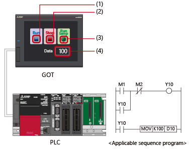
<Settings of GOT for objects>
| No. | Name | Object type | Description |
|---|---|---|---|
| (1) | Run switch | Switch | Device: M1 Operation: Bit momentary |
| (2) | Stop switch | Switch | Device: M2 Operation: Bit momentary |
| (3) | Run lamp | Lamp | Device: Y10 |
| (4) | Data | Numerical input | Device: D10 Format: Unsigned decimal |
<Device type used in the sequence program>
| No. | Device | Type |
|---|---|---|
| (1) | M1 | Bit device |
| (2) | M2 | Bit device |
| (3) | Y10 | Bit device |
| (4) | D10 | Word device |