IoT-related Products NC Virtual Simulator

High-fidelity simulator digitizes the processes from product designing to trial machining, improving work efficiency and productivity.
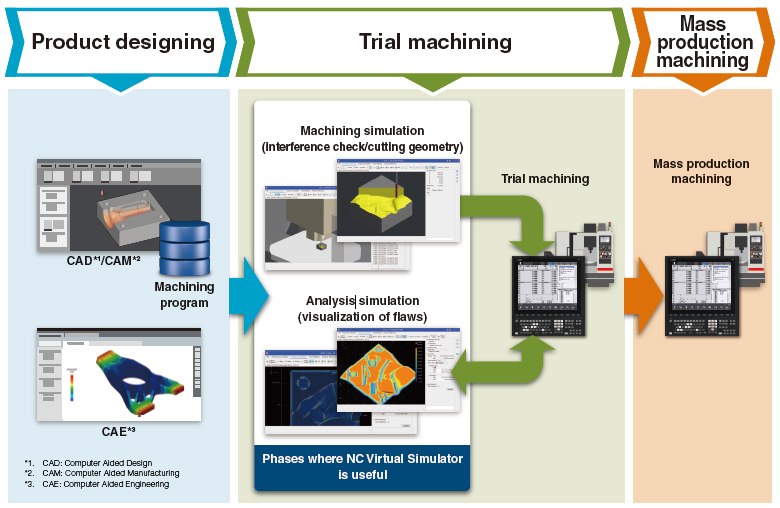
NC Virtual Simulator makes it possible to check at designing stage the machining errors that could previously only be found at trial machining stage, thus reducing the time and effort required for machining trials.
Reduce machining trials with high-fidelity simulation
Diverse features allow you to validate machining programs, verify work instruction data, and analyze the flaws in the surface finish to help you identify and correct issues at trial machining stage.
Workpiece simulation, Machine simulation
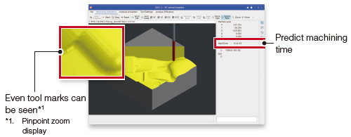
Machining time is calculated accurately using digital position data that factors in smoothing, acceleration/deceleration, and servo response delay.
The surface geometry depicted in a higher resolution allows for safe and quick validation of machining programs.
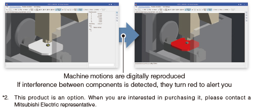
You can check whether machine interference occurs during automatic operation using a machine model.
If interference is detected, the interfering components turn to the interference color to alert you. *2
Analysis simulation
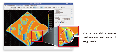
①Color map display
The change in the speed, the acceleration rate, the speed difference between adjacent segments and other data is plotted as color map.
It helps you identify where a machining error occurs.
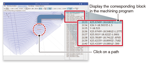
②Program link display
You can identify the corresponding block in the machining program by selecting a segment in the simulated surface. This makes it easy to check and correct the machining program block for the segment with a problem you detect in color map display.
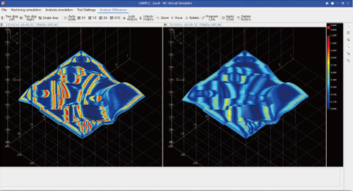
Simulation comparison display
Simulation result is compared with previous result retained as history. You can check how machining result changes with different machining conditions such as NC parameters.
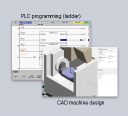
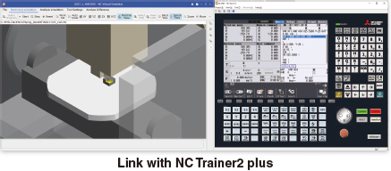
Machine design can be simulated by linking with NC Trainer2 plus
NC Virtual Simulator can also be used in machine design and user PLC development by machine tool builders when linked with NC Trainer2 plus.
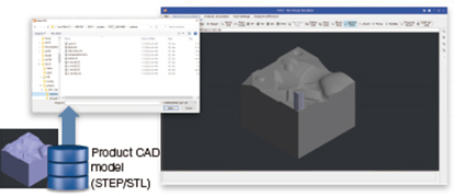
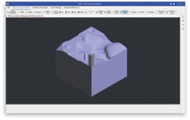
CAD model superimposition
Product CAD models (STEP/STL) can be loaded and superimposed with the workpiece simulation to check if there are missing machining processes.
System requirements
| Item | Description |
|---|---|
| Computer | A personal computer with a processor with a clock speed of 2.66 GHz or faster, 2 or more cores and 4 or more threads (4 or more cores and 8 or more threads are recommended) |
| Memory | 8 GB or greater |
| Available hard disk space | 4 GB or greater (excluding the space required for OS operation) |
| OS | Windows ® 10 or newer (64-bit) *3 |
| Interface | 10/100/1000M Ethernet (only for network-connected version) USB 1.1 or later |
| Display | A video adapter and a monitor with a resolution of HDTV (720p) (1280×720) or better (at least 65536 colors; 16770000 colors is recommended) PC with OpenGL 4.5 or later display adapter |
| Supported language | Japanese/English |
| Machine | Machining center |
| Supported CNCs | M800VW/M800VS/M80V/M800W/M800S/M80 Series *4 |
- *3. WOW64 is used
- *4. Not compatible with M80VW and M80W