Sensing Module Features

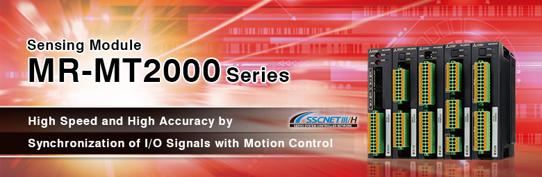
MR-MT2000Series
- Concept
- Application examples to increase speed and accuracy
- Functions List
- Applicable controllers
- Components
Concept
Increasing speed and accuracy of equipment by synchronization of the motion control cycle with I/Os, such as a general-purpose pulse train driver, sensor I/O, and shutter I/O
- ■I/O with a fastest response time of 1μs
- ■Pulse I/O for synchronous control
- ■High-accuracy analog I/O
- ■Supporting open standard encoder I/Fs
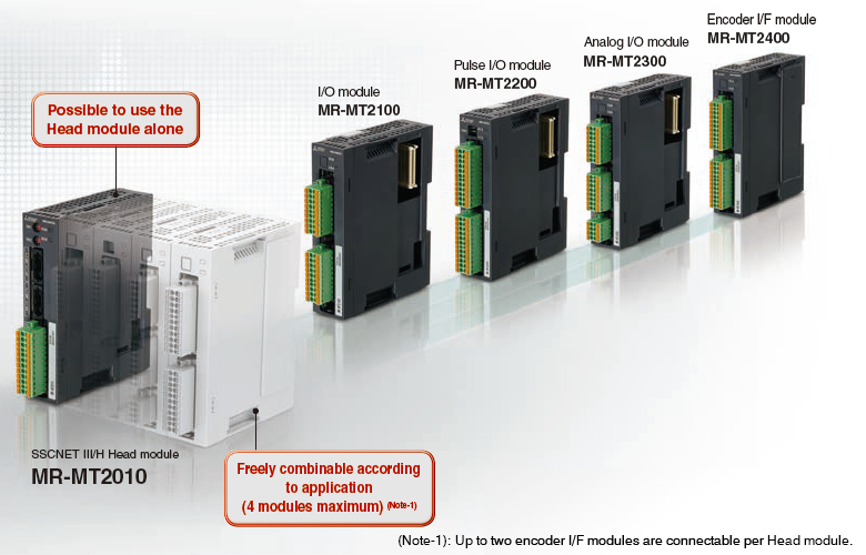
 Place the mouse cursor on each module picture to display its features and specifications.
[Application example in printing processes]
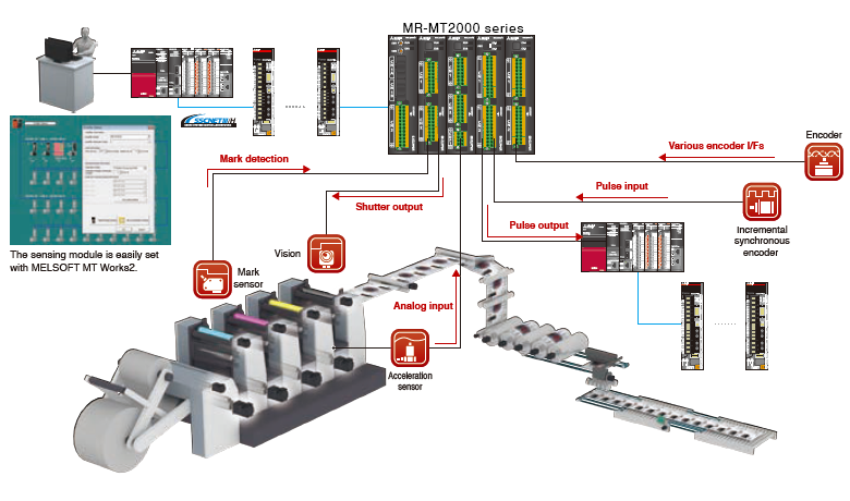
Place the mouse cursor on ![]() to display the module to be used.
to display the module to be used.
Application examples to increase speed and accuracy
Application examples with the MR-MT2000 series


Click each image of "Issue" to see details of the corresponding application example.
Functions List
| Name | Item | Specification | ||
|---|---|---|---|---|
| SSCNETIII/H Head module MR-MT2010 |
Control circuit power supply input |
Voltage | 24 V DC | |
| Permissible voltage fluctuation | 24 V DC ± 10 % | |||
| Current capacity | 1.0 A | |||
| Communications interface | SSCNET III/H | |||
| DI | Number of input points | 12 points | ||
| Input method | Sink input/source input (photocoupler isolation) | |||
| Input response time | ON to OFF: within 1 μs/OFF to ON: within 1 μs | |||
| DO | Number of output points | 2 points | ||
| Output method | Sink output (photocoupler isolation) | |||
| Output response time | ON to OFF: within 1 μs/OFF to ON: within 1 μs | |||
| Mass [kg] | 0.2 | |||
| I/O module MR-MT2100 |
DI | Number of input points | 16 points (Note-1) | |
| Input method | Sink input/source input (photocoupler isolation) | |||
| Input response time | ON to OFF: within 1 μs/OFF to ON: within 1 μs | |||
| DO | Number of output points | 16 points (Note-1) | ||
| Output method | Sink output/source output (photocoupler isolation) | |||
| Output response time |
Sink output | ON to OFF: within 1 μs/OFF to ON: within 1 μs | ||
| Source output |
ON to OFF: within 2 μs/OFF to ON: within 1 μs | |||
| Mass [kg] | 0.2 | |||
| Pulse I/O module MR-MT2200 |
Number of pulse I/O channels | Output 2CH, input 2CH, I/O 1CH each (selectable) | ||
| Pulse output | Output signal | Differential line driver output/open collector output | ||
| Output method | Forward/reverse rotation pulse train, signed pulse train, A-phase/B-phase pulse train | |||
| Maximum frequency |
Differential line driver output |
4M pulse/s (A-phase/B-phase pulse train 4 multiples) 1M pulse/s (forward/reverse rotation pulse train, signed pulse train) |
||
| Open collector output |
200k pulse/s (A-phase/B-phase pulse train 4 multiples) 50k pulse/s (forward/reverse rotation pulse train, signed pulse train) |
|||
| Pulse input | Input signal | Differential line driver input | ||
| Input method | Forward/reverse rotation pulse train, signed pulse train, A-phase/B-phase pulse train | |||
| Maximum frequency |
Differential line driver input |
4M pulse/s (A-phase/B-phase pulse train 4 multiples) 1M pulse/s (forward/reverse rotation pulse train, signed pulse train) |
||
| DI | Number of input points | 7 points per axis (total of 14 points) | ||
| Input method | Sink input/source input (photocoupler isolation) | |||
| DO | Number of output points | 5 points per axis (total of 10 points) (Note-2) | ||
| Output method | Sink output/source output (photocoupler isolation) | |||
| Mass [kg] | 0.2 | |||
| Analog I/O module MR-MT2300 |
Analog input | Number of input channels | 4CH | |
| Input voltage range | -10 to 10 V DC/-5 to 5 V DC (selectable) | |||
| Resolution | ± 10 V range: 0.334 mV ± 5 V range: 0167 mV | |||
| Conversion accuracy | ± 0.1 % (at 25 ℃)/± 0.3 % (at 0 ℃ to 60 ℃) | |||
| Analog output | Number of output channels | 4CH | ||
| Output voltage range | -10 to 10 V DC | |||
| Resolution | ± 10 V range: 0.319 mV | |||
| Conversion accuracy | ± 0.4 % (at 25 ℃)/± 0.5 % (at 0 ℃ to 60 ℃) | |||
| Mass [kg] | 0.2 | |||
| Encoder I/F module MR-MT2400 |
Number of encoder channels | 2CH (Note-3) | ||
| Supported encoder communications | SSI, Mitsubishi Electric serial I/F | |||
| Mass [kg] | 0.2 | |||
- (Note-1): When the module is used at the temperature exceeding 55 ℃ and up to 60 ℃, keep the number of points turned on simultaneously to be 14 or less for each DI and DO.
- (Note-2): Two of the five points and the pulse output (open collector output) are mutually exclusive.
- (Note-3): Different encoder interfaces cannot be inputted for each channel. The same encoder interface should be used for both two channels.
Applicable controllers
| Motion CPU module | R64MTCPU, R32MTCPU, R16MTCPU |
|---|---|
| Position board | MR-MC200 series, MR-MC341 |
Components
| Part | Model | Description | Standards |
|---|---|---|---|
| SSCNET III/H Head module |
MR-MT2010 | SSCNET III/H, input: 12 points, output: 2 points | UL, CE, KC, EAC |
| I/O module | MR-MT2100 | Input 16 points, output 16 points | UL, CE, KC, EAC |
| Pulse I/O module | MR-MT2200 | Total pulse I/O: 2CH | UL, CE, KC, EAC |
| Analog I/O module | MR-MT2300 | Analog input: 4CH, analog output: 4CH | UL, CE, KC, EAC |
| Encoder I/F module | MR-MT2400 | Encoder I/F: 2CH | UL, CE, KC, EAC |