FR-A800 Plus Series
System configuration diagram
Communication with the host controller: CC-Link, communication with the distance meter: RS-422
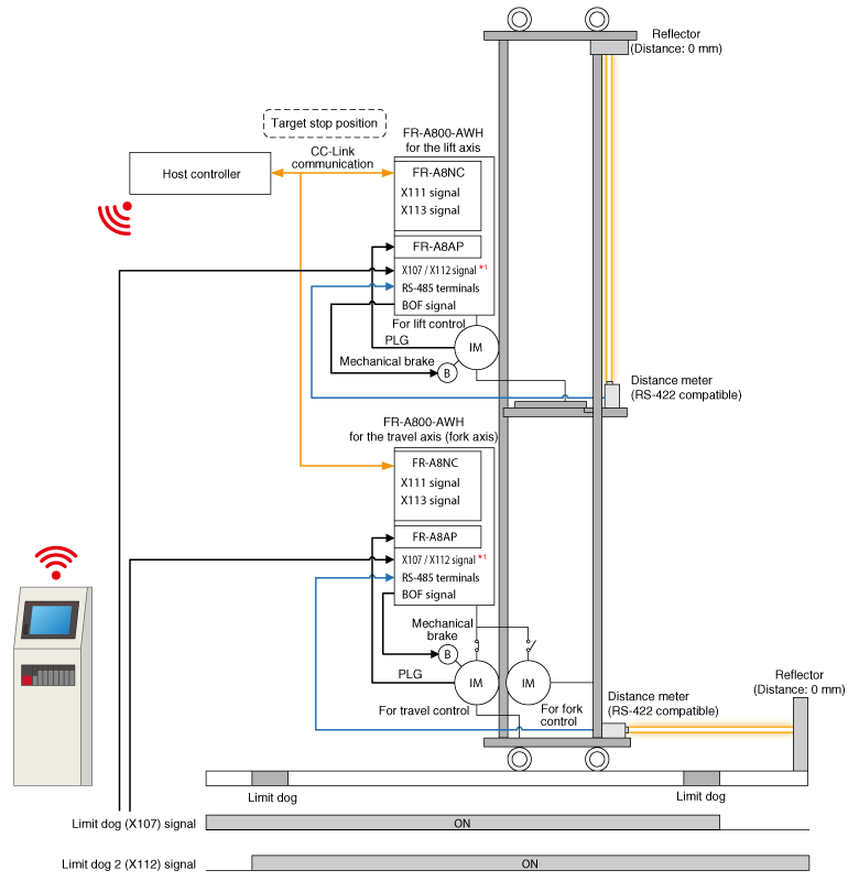
*1: To use the inverter safely, it is recommended to use the Limit dog (X107) signal and the Limit dog 2 (X112) signal.
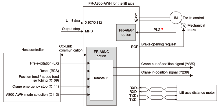
Terminal connection diagrams
Wiring example of a lift axis inverter
Wiring example of a travel/fork axis inverter
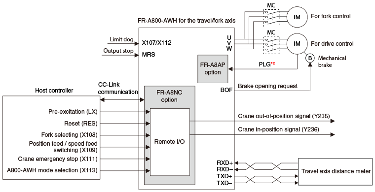
*2: A separate power supply of 5 V / 12 V / 15 V / 24 V is necessary according to the encoder power specification.