Inverters-FREQROL-E Series -FREQROL-E800- Downtime reduction

Downtime reduction
When a fault occurs, AI analysis and other diagnosis functions solve the problem quickly.

Streamlining the installation process E800 E800-E E800-SCE
Compatible installation size
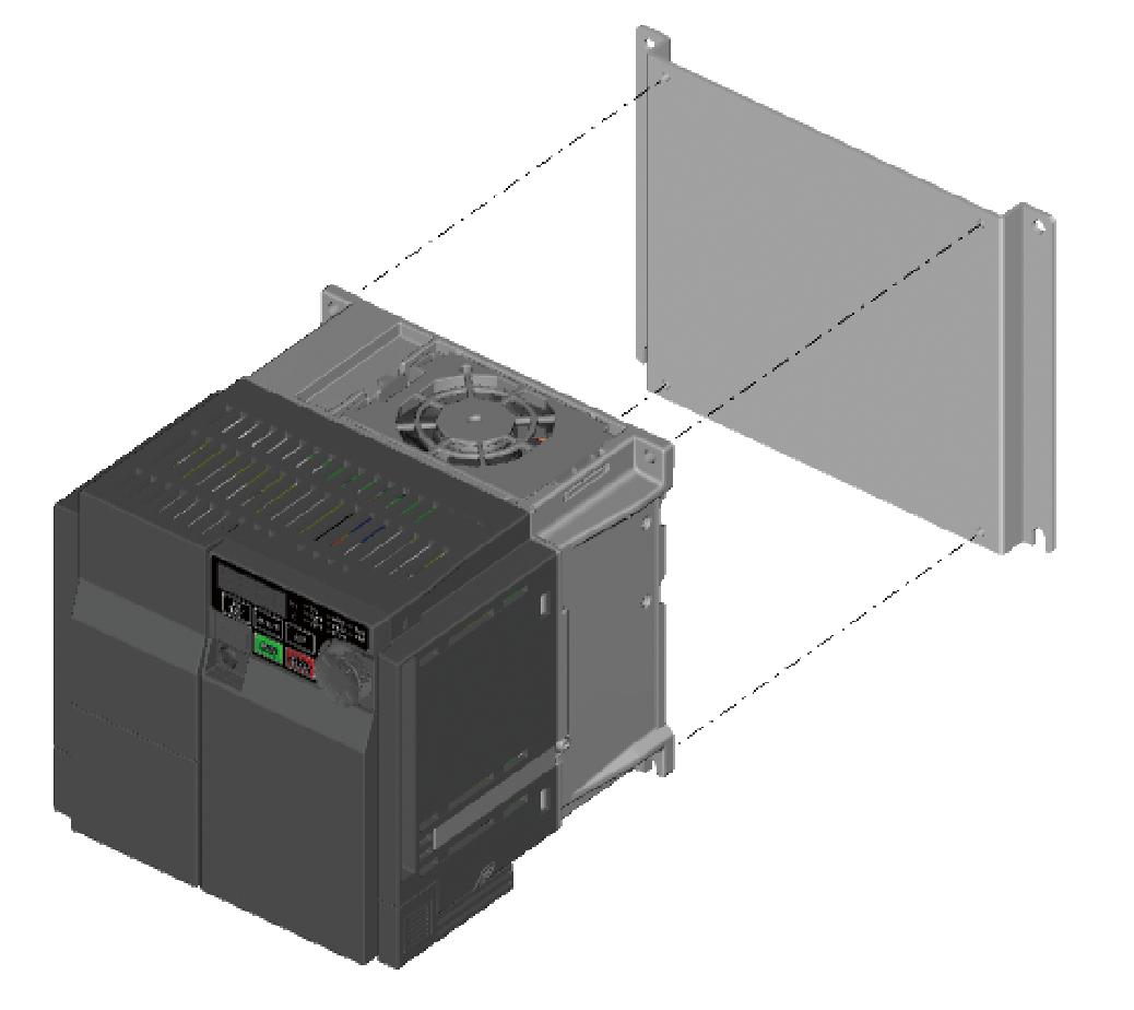
The installation size was determined to assure exchangeability with the FR-E700 series. Installation interchange attachment options are available for facilitating replacement with the models of different size.
(The depth required for installation increases by 12 mm.)
Easy and fast wiring E800 E800-E E800-SCE
Control circuit terminal
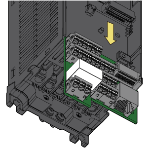
- Spring clamp terminals have been adopted for control circuit terminals for easy wiring.
Furthermore, wires can be protected against loosening or contact faults due to vibrations during operation on a bogie or during transport. No additional screw tightening is required. - The removable control circuit terminal block facilitates replacement with a new one.
| FR-E800 | FR-E800-E | FR-E800-SCE | ||
|---|---|---|---|---|
| Input terminal | 7 | 2 | 0 | |
| Output terminal | Open collector | 2 | 0 | 0 |
| Relay | 1 | 1 | 1 | |
Troubleshooting supported by AI technology E800 E800-E E800-SCE
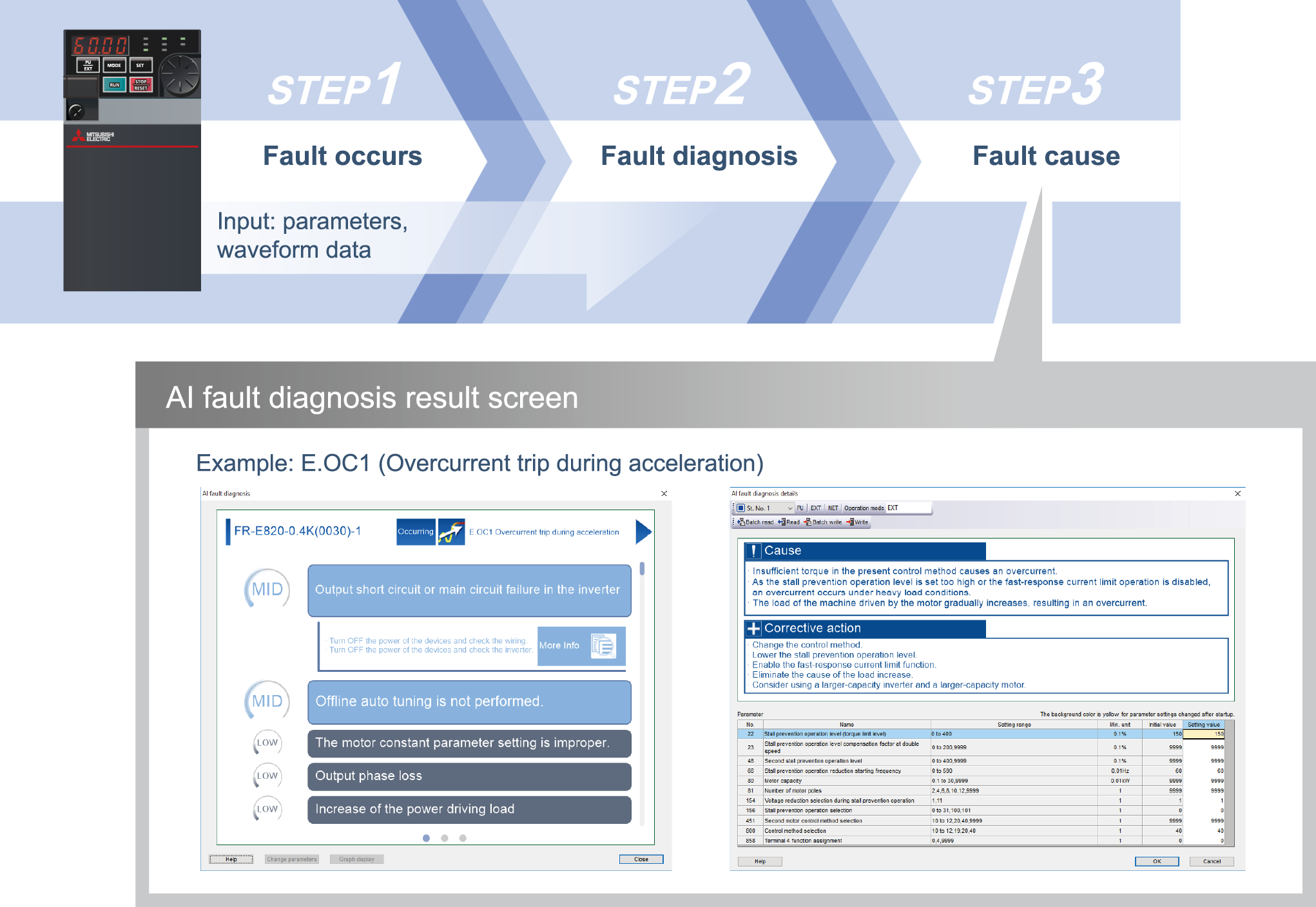
AI fault diagnosis
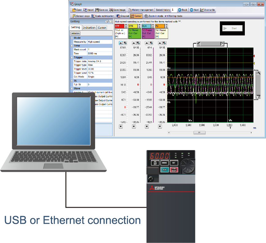
The inverter is connected to the engineering software FR Configurator2 (USB/Ethernet connection).
Maisart *1 (Mitsubishi Electric's AI technology) is integrated in the software to analyze data and help identify the cause of a fault *2 (this function is enabled during speed control).
This function enables the fastest troubleshooting procedure without requiring any special skills, which contributes to downtime reduction.
- *1 Maisart is Mitsubishi Electric's brand of AI technology. The name stands for "Mitsubishi Electric's AI creates the State-of-the-ART in technology". This means that it is using our proprietary AI technology to make everything smarter.
- *2 Diagnosable faults: Overcurrent trip, Overvoltage trip, Inverter overload trip (electronic thermal relay function), Motor overload trip (electronic thermal relay function). (other faults will be supported in the future.)
Continuing the operation during a trouble E800 E800-E E800-SCE
Emergency drive (Fire mode)
The inverter can continue driving the motor in case of emergency such as a fire, since protective functions are not activated even if the inverter detects a fault.
Using this function may damage the motor or inverter because driving the motor is given the highest priority. Use this function for emergency operation only.
The operation can be switched to the commercial power supply operation at the occurrence of a fault which may cause damage of the inverter.

Quick reaction to troubles E800 E800-E E800-SCE
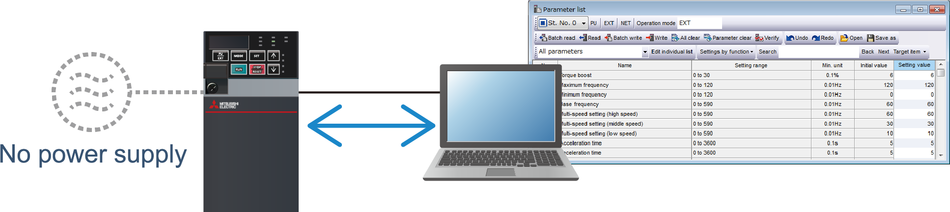
Power supply from USB port
With the power supplied from the computer (USB bus power connection) *3 , parameters can be set using FR Configurator2 while the main circuit power supply is OFF.
Maintenance can be performed quickly and safely.
*3 The maximum SCCR should be 500 mA. A PU connector cannot be used during USB bus power connection.
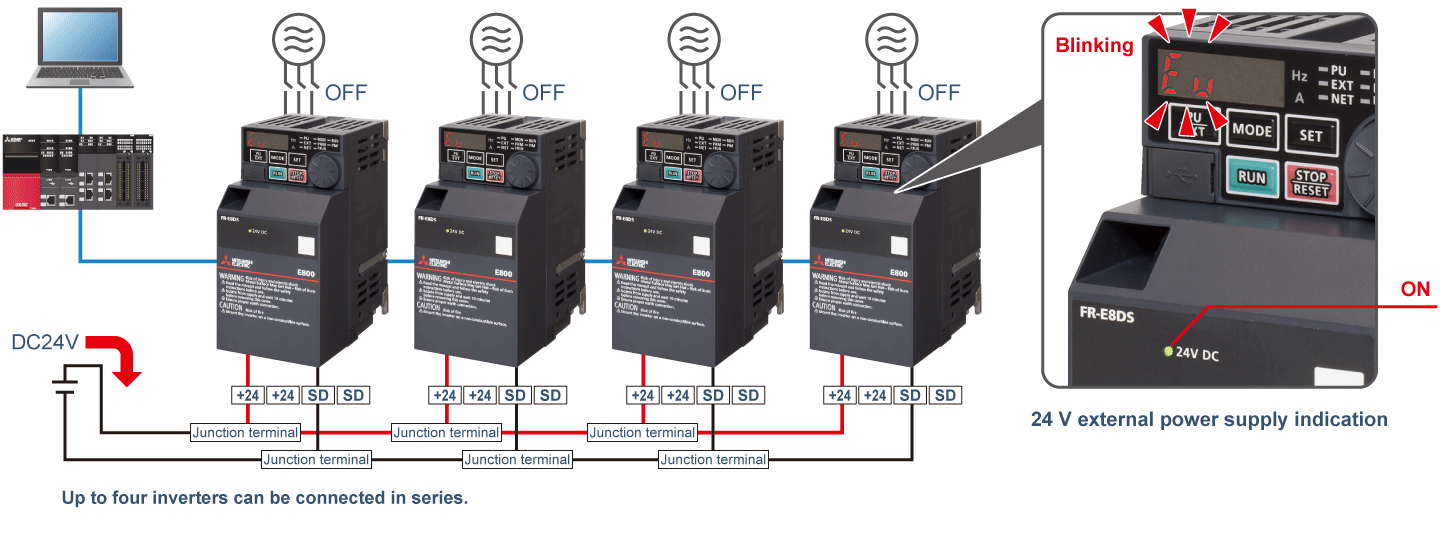
24 VDC input (FR-E8DS E kit)
Maintenance can be performed safely as the parameter setting and communication operation can be done while the main circuit power is OFF. (24 V external power supply operation)
When a fault occurs, troubleshooting is facilitated as the fault indication remains after turning OFF the main circuit power supply.
Turning ON the main circuit power during the 24 V external power supply operation switches the operation to the normal operation. Before the operation is switched, a reset is performed in the inverter.
Trouble analysis from a remote location E800 E800-E E800-SCE
Trace function
The operating status (output frequency or other data) immediately before the protective function is activated can be stored in a data file.
Users can read the data file in FR Configurator2 for graph display or send it by e-mail to someone away from the worksite, which facilitates the trouble analysis.
Clock function
Setting the time *4 enables the user to specify the protective function activation time. The date and time are also saved with the trace data, making the fault analysis easier. Time synchronization via CC-Link IE TSN communication is available for the Ethernet model.
It is possible to synchronize the internal clocks of the devices that comprise the CC-Link IE TSN communication.
- *4 The clock does not run while the control circuit power is OFF. The clock needs to be set every time after turning ON the inverter power.
By using the real-time clock function with the optional LCD operation panel (FR-LU08) (when using battery), the clock keeps running even when the control power supply is turned OFF.