MELSERVO-J4 Series Servo Amplifier Model Designation

- Model Designation for 1-Axis Servo Amplifier
- Model Designation for Multi-Axis Servo Amplifier
- Model Designation for Drive Unit
- Model Designation for Power Regeneration Converter Unit
- Model Designation for Resistance Regeneration Converter Unit
- Related Link
Model Designation for 1-Axis Servo Amplifier (Note 14)
GF GF-RJ B B-RJ A A-RJ
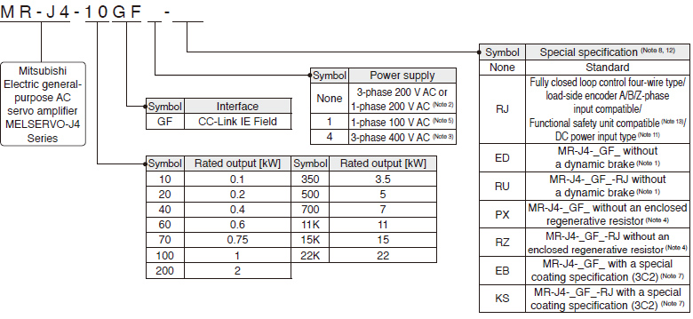
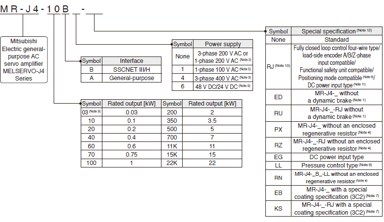
- Notes: 1. Dynamic brake which is built in 7 kW or smaller servo amplifiers is removed. When the servo amplifiers without the dynamic brake are used, the servo motors coast to a stop and do not stop immediately at alarm occurrence or power failure. Take measures to ensure safety on the entire system. When specified servo motors are used, the electronic dynamic brake may activate at an alarm occurrence. The dynamic brake can be disabled with a servo parameter setting. Refer to relevant Servo Amplifier Instruction Manual for details.
- 2. A power supply of 1-phase 200 V AC is supported by 0.1 kW to 2 kW servo amplifiers.
- 3. A power supply of 3-phase 400 V AC is supported by 0.6 kW and 1 kW or larger servo amplifiers.
- 4. Available in 11 kW to 22 kW servo amplifiers. A regenerative resistor (standard accessory) is not enclosed. Refer to relevant Servo Amplifier Instruction Manual for details.
- 5. A power supply of 1-phase 100 V AC is supported by 0.1 kW to 0.4 kW servo amplifiers.
- 6. MR-J4-_B_-LL is available. Refer to "MR-J4-_B_-LL MR-J4-DU_B_-LL Servo Amplifier Instruction Manual" for the pressure control compatible servo amplifiers.
- 7. The special coating (IEC 60721-3-3:1994 Class 3C2) is applied to the circuit board of the servo amplifier. Refer to relevant Servo Amplifier Instruction Manual for details.
- 8. Positioning mode is supported by MR-J4-GF(-RJ)/MR-J4-A-RJ servo amplifiers.
- 9. Supported by MR-J4-03A6(-RJ) servo amplifier.
- 10. Only positioning mode is supported by MR-J4-03A6-RJ. The fully closed loop control, load-side encoder A/B/Z-phase input, and the functional safety unit are not supported.
- 11. Only 200 V is available.
- 12. For the servo amplifier software version which supports each function, refer to the specification page of each unit.
- 13. When the servo amplifier is connected to CC-Link IE Field Network Basic, an MR-D30 functional safety unit is not supported.
- 14. This section describes what each symbol in a model name indicates. Some combinations of symbols are not available.
Model Designation for Multi-Axis Servo Amplifier (Note 8)
WB
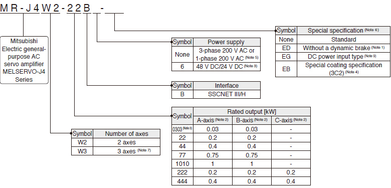
- Notes: 1. Dynamic brake which is built in servo amplifiers is removed. When the servo amplifiers without the dynamic brake are used, the servo motors coast to a stop and do not stop immediately at alarm occurrence or power failure. Take measures to ensure safety on the entire system. When specified servo motors are used, the electronic dynamic brake may activate at an alarm occurrence. The dynamic brake can be disabled with a servo parameter setting. Refer to relevant Servo Amplifier Instruction Manual for details.
- 2. A-axis, B-axis, and C-axis indicate names of axes of the multi-axis servo amplifier. The C-axis is available for the 3-axis servo amplifier.
- 3. Supported by MR-J4W2-0303B6 servo amplifier.
- 4. The special coating (IEC 60721-3-3:1994 Class 3C2) is applied to the circuit board of the servo amplifier and the drive unit of 30 kW or larger. Refer to relevant Servo Amplifier Instruction Manual for details.
- 5. A power supply of 1-phase 200 V AC is supported by 0.2 kW to 0.75 kW servo amplifiers.
- 6. For the servo amplifier/drive unit software version which supports each function, refer to the specification page of each unit.
- 7. Available only with 0.2 kW and 0.4 kW.
- 8. This section describes what each symbol in a model name indicates. Some combinations of symbols are not available.
- 9. Contact your local sales office for more details.
Model Designation for Drive Unit
B B-RJ B-RJ100 A A-RJ
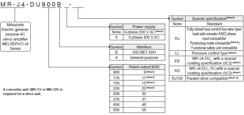
- Notes: 1. The special coating (IEC 60721-3-3:1994 Class 3C2) is applied to the circuit board of the servo amplifier and the drive unit of 30 kW or larger. Refer to relevant Servo Amplifier Instruction Manual for details.
- 2. A power supply of 3-phase 200 V AC is supported by 37 kW or smaller drive units.
- 3. Available only with MR-J4-DU_B_(-RJ).
- 4. Positioning mode is supported by MR-J4-DU_A_-RJ drive unit.
- 5. MR-J4-DU_B_-LL is available in 30 kW or larger drive units. Refer to "MR-J4-_B_-LL MR-J4-DU_B_-LL Servo Amplifier Instruction Manual" for the pressure control compatible servo amplifiers.
- 6. For the servo amplifier/drive unit software version which supports each function, refer to the specification page of each unit.
- 7. Available only with the drive unit of 3-phase 400 V AC and 45 kW or higher.
- 8. Refer to " Compatible Controllers " for compatible controllers.
Model Designation for Power Regeneration Converter Unit (Note 1, 3)
B B-RJ B-RJ100

- Notes: 1. The power regeneration converter unit is supported by MR-J4-DU_B(4)(-RJ) and MR-J4-DU_B4-RJ100 drive units. It is not supported by MR-J4-DU_A(4)(-RJ) drive unit. Refer to "MR-CV_ MR-CR55K_ MR-J4-DU_B_(-RJ) MR-J4-DU_A_(-RJ) Instruction Manual" for the combination with MR-J4-_B(4)(-RJ) servo amplifiers.
- 2. Available only with the power regeneration converter unit of 400 V.
- 3. This section describes what each symbol in a model name indicates. Some combinations of symbols are not available.
Model Designation for Resistance Regeneration Converter Unit (Note 1, 3)
B B-RJ A A-RJ
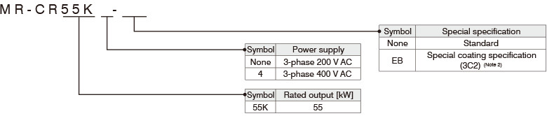
- Notes: 1. One unit of resistance regeneration converter unit is required for each drive unit.
- 2. The special coating (IEC 60721-3-3:1994 Class 3C2) is applied to the circuit board of the resistance regeneration converter unit. Refer to "MR-CV_ MR-CR55K_ MR-J4-DU_B_(-RJ) MR-J4-DU_A_(-RJ) Instruction Manual" for details.
- 3. Use the resistance regeneration converter unit with MR-J4-DU_B(4)(-RJ) or MR-J4-DU_A(4)(-RJ) unit. The resistance regeneration converter unit is not compatible with MR-J4-DU_B4-RJ100 and 22 kW or smaller MR-J4-DU_B(4)(-RJ).