Human-Machine Interfaces(HMIs)-GOT GOT2000 Series

GOT Drive Control (Servo) Interactive Solutions
GOT Drive Control (Servo) Interactive Solutions
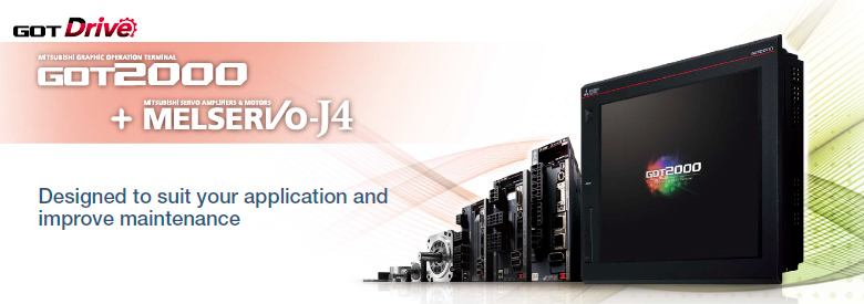
The GOT2000 provides advanced functionality and improves connectivity with Mitsubishi servo systems.
It provides some functions of MR Configurator2 (supporting MR-J5 and MR-J4).
The GOT Drive enhanced functionality is designed to eliminate need for additional hardware, software and suits customers’ applications to speed up system startup, improve maintenance and troubleshooting.
GOT and servo system configurations
■System configuration features
- Command interface: CC-Link IE TSN
- Control mode: positioning control, direct control
- Program
Programmable controller CPU: ladder, FBD/LD, ST language
Motion module: ST language - Max. number of control axes
RG78G: 4/8/16/32/64 axes
RG78GH *1 : 128/256 axes
FX5- SSC-G: 4/8 axes
*1 When MR-JET-G servo ampliers are used for all axes, the maximum number of the control axes is 120.

■System configuration features
- Command interface: CC-Link IE TSN
- Control mode: positioning control, direct control
- Program
Programmable controller CPU: ladder, FBD/LD, ST language
Motion module: ST language - Max. number of control axes
RG78G: 4/8/16/32/64 axes
RG78GH *1 : 128/256 axes
FX5- SSC-G: 4/8 axes
*1 When MR-JET-G servo amplifiers are used for all axes, the maximum number of the control axes is 120.
■System configuration features
- Command interface: CC-Link IE Field Network Basic
- Control mode: positioning control, direct control
- Program
Programmable controller CPU: ladder, FBD/LD, ST language - Max. number of control axes: 16/32/64 axes
■System configuration features
- Command interface: pulse train
- Control mode: positioning control, speed control, torque control
- Program: sequence program (ladder)
- Max. number of control axes: 1/2/4/8 axes
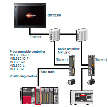
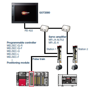
■System configuration features
- Command interface: pulse train
- Control mode: positioning control
- Program: sequence program (ladder)
- Max. number of control axes: 1/2/4/8/32 axes
* Cannot be used in the MR-J3 compatible mode.

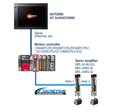
■System configuration features
- Command interface: SSCNET III/H
- Control mode: positioning control, synchronous control, speed control, torque control, tightening & press-fit control, cam control
- Program: sequence program (ladder)
- Max. number of control axes: 2/4/8/16 axes
* Cannot be used in the MR-J3 compatible mode.

■System configuration features
- Command interface: SSCNET III/H
- Control mode: positioning control, synchronous control, speed control, torque control, tightening & press-fit control, cam control
- Program: motion program (SFC)
- Max. number of control axes: 16/32/64 axes
* Cannot be used in the MR-J3 compatible mode.

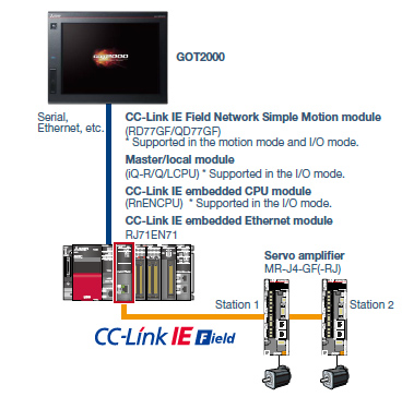
■System configuration features
- Command interface: CC-Link IE Field Network
- Control mode: positioning control, synchronous control, speed control, torque control, cam control
- Program: sequence program (ladder)
- Max. number of control axes: 4/8/16/32 axes
Drive Control (Servo) Interactive Solutions Movie
Drive control interactive functions and supported models
Supported drive control interactive functions differ depending on the system configuration.
For the details, please refer to the
Drive control interactive functions and supported models
| Related materials | ||
|---|---|---|
|
|
GOT2000 Drive Control (Servo) Interactive Solutions < Contents > Advanced drive control connectivity provides additional value to your system See details of GOT2000 Drive Control (Servo) Interactive Solutions |
Created : Size : (PDF) |