
How to use LTspice® models
This document describes how to use the LTspice model provided by Analog Devices, Inc. By performing analog circuit simulations using LTspice, it is possible to check the detailed waveforms of voltage and current in the static and dynamic characteristics of power devices, which can be useful for the design of power electronics equipment. Below, we will outline the process from downloading the model to executing the simulation.
LTspice® is a registered trademark of Analog Devices, Inc.
1. Location of the Model and Download Method
(1) Location of the Model
・Please visit the following URL to access the simulator's listing page.
< https://www.mitsubishielectric.com/semiconductors/powerdevices/design_support/simulator/ >
・After filling in the required information and agreeing to the disclaimer, you will be redirected to the
download page.
(2) Downloading the Model
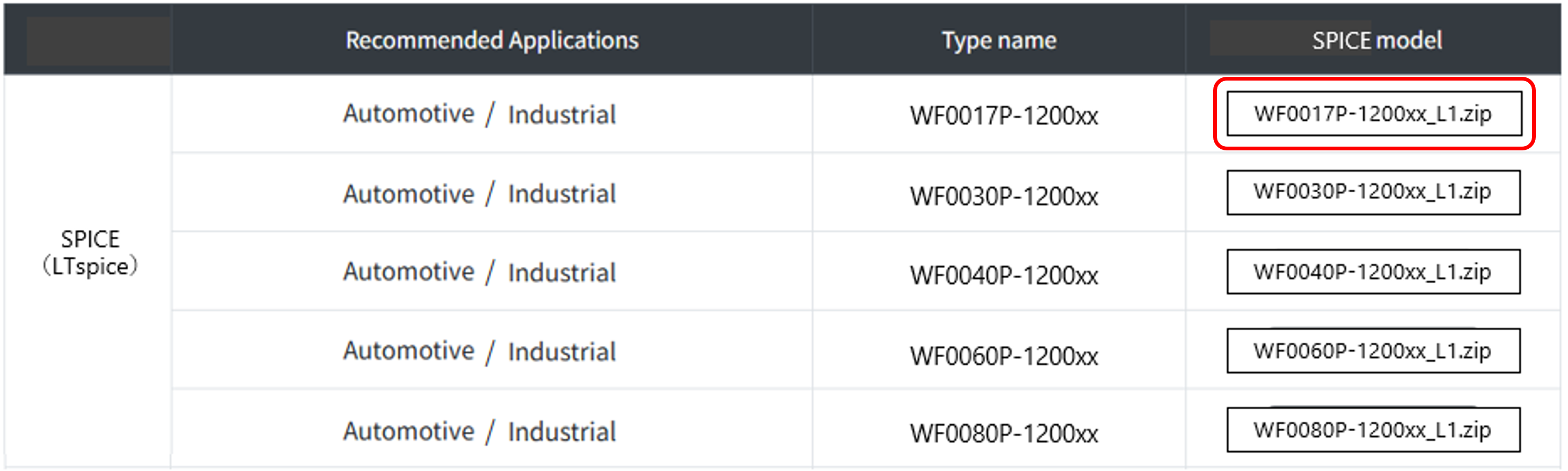
・Following table 1 lists the zip files of LTspice models corresponding to the model names of power devices.
・When using the LTspice model, it is necessary to download the LTspice model that corresponds to the model name of the power device you are simulating.
・In this case, we will use the SiC-MOSFET"WF0017P-1200x"and check the switching waveform.
・Please download"WF0017P-1200xx.zip"and temporarily store them in an appropriate location, such as your desktop.
Table 1. Model Listings (Example)
2. Storing the Model
Save the LTspice model in a folder.
・Create an appropriate folder and place"WF0017P-1200xx_L1.zip"and"Chip.asy"from"WF0017P-1200xx_L1.zip"into it.
・This time as an example, we will create a folder named"WF0017P-1200xx"on the desktop, as shown in Figure 1, and move the file there.
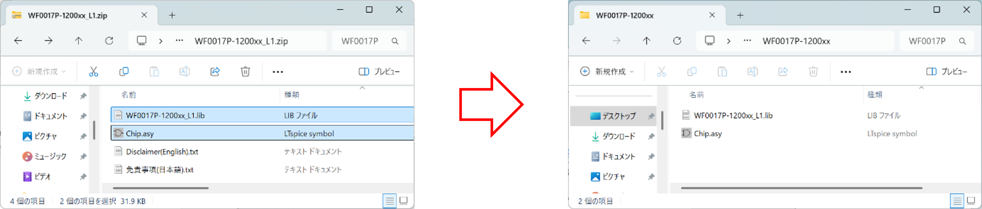
Figure 1. Model Storage (Example)
・When you open"WF0017P-1200xx_L1.lib"and "Chip.asy", they will look like Figure 2 and Figure 3, respectively.
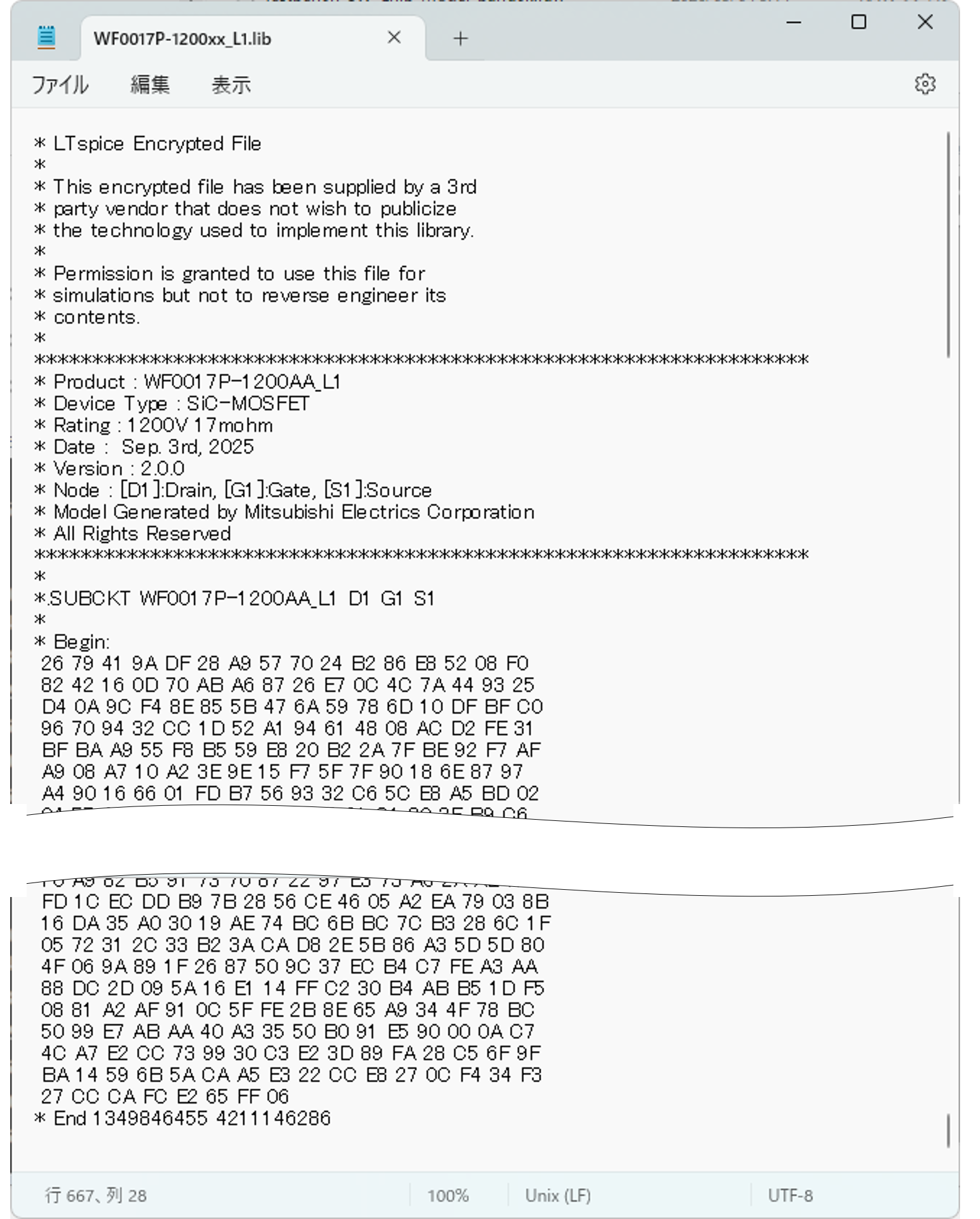
Figure 2. WF0017P-1200xx_L1.lib
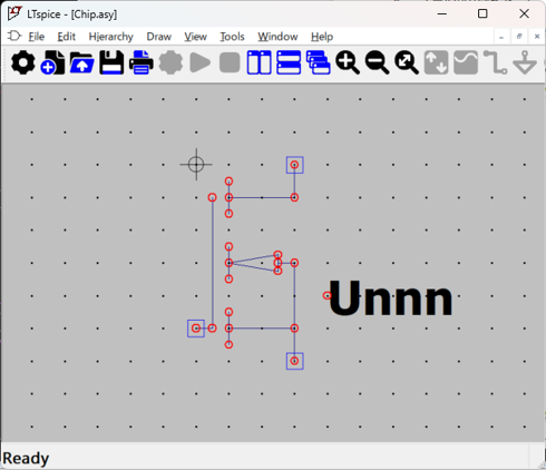
Figure 3. Chip.asy
3. Model placement
For this example, we'll add the SiC-MOSFET model "WF0017P-1200xx_L1.lib" to the circuit diagram.
(Note: This time, we're using test_wf0017p-1200xx.asc as the circuit diagram, but it's not included. Please use your own circuit diagram.)
① Click the "Component" icon on the LTspice toolbar and select "Chip.asy" from the "WF0017P-1200xx" folder we saved this time.
② Place it in the desired location on the circuit diagram. (There are two locations in this example.)
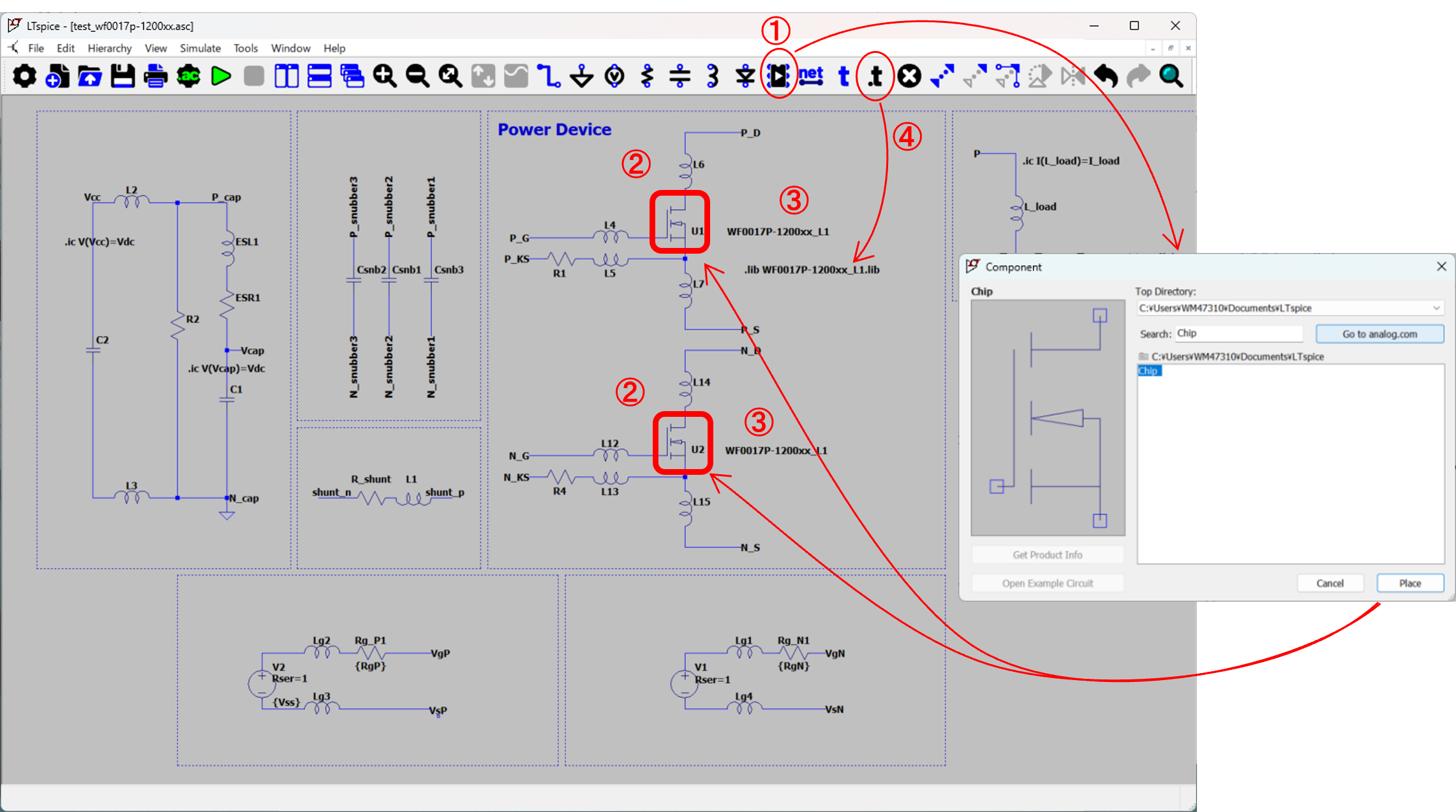
Figure 4. Placement on LTspice schematic (Example)
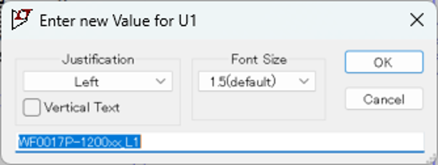
③ Enter the Value of the placed MOSFET as"WF0017P-1200xx_L1".
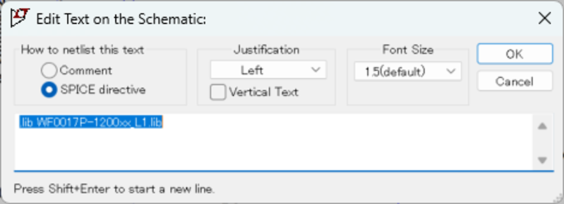
④ Click"SPICE Directive"on the toolbar and enter ".lib WF0017P-1200xx_L1.lib".
4. Execution of Simulation and Display of Results
① Click "Run" on the LTspice toolbar to execute the simulation.
② When you specify the voltage and current at the point you want to measure, the waveform shown below will be output.
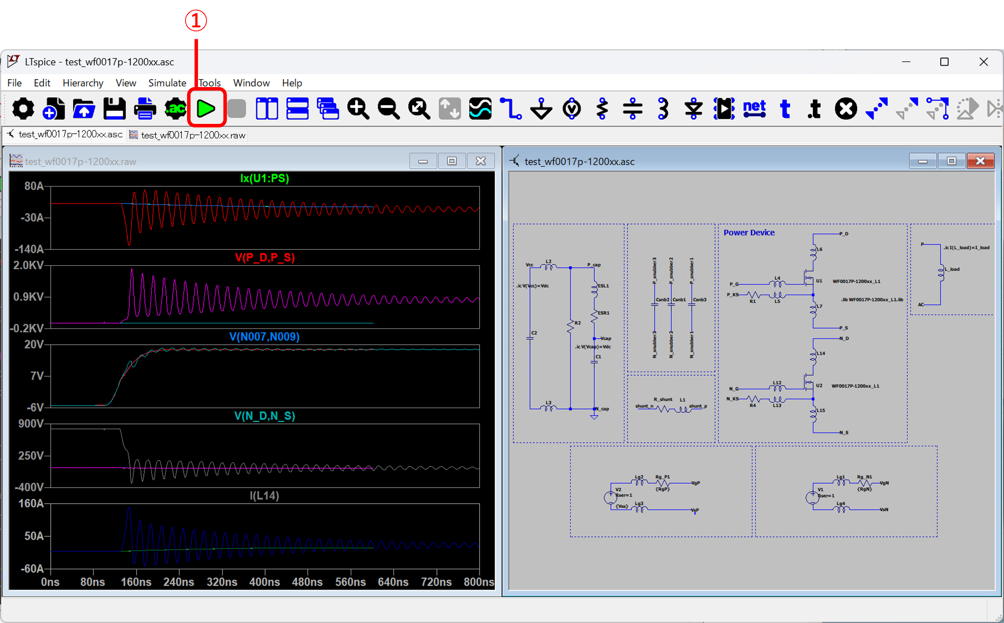
Figure 5. Simulation Execution Results