Improving productivity on production lines
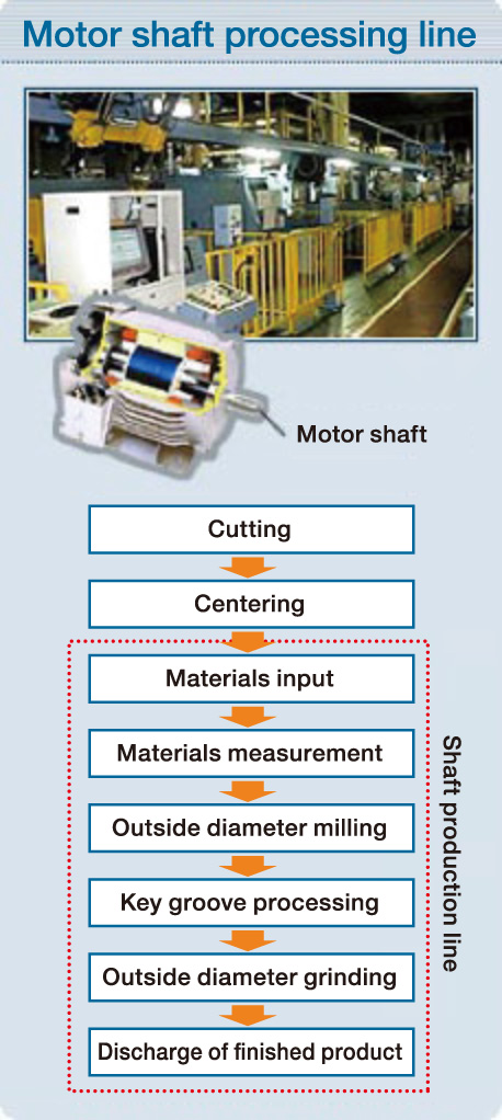
The e-F@ctory FA (factory automation) integrated solution has been introduced on a motor shaft processing line at Mitsubishi Electric’s Shinshiro Factory, which handles a large quantity of non-standard products. This change has improved productivity by enabling a high number of low-volume production runs on reduced lead times.
Proving its effectiveness, Mitsubishi Electric operates the e-F@ctory solution within its own production facilities. This allows the business to verify improvements in productivity and operating rates, which is essential to both validate and improve the e-F@ctory concept. As part of this, the company is promoting the creation of optimal production systems, which includes implementing Mitsubishi Electric FA products to process and link shop floor data with management information, as well as introducing joint solutions with manufacturing partners.
Key points of this case study
- 1. Touch panel displays (GOT HMIs) allow monitoring of the operating status for the entire line, error history management, and the visualization of the factory.
- 2. Enabling the automated scheduling and communication of processing information between facilities has reduced setup times and expanded the scope of unmanned operation.
INDEX
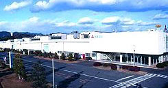
Introduction to the Shinshiro Factory
Established in 1974 as a branch of the Nagoya Works, the Shinshiro Factory uses state-of-the-art mechatronics and systems technology to produce three-phase motors. As a specialist in motor production, it manufactures both standard and special purpose motors in small and medium sizes.
In recent years, customer requirements for electric motors have diversified, due to the rapid pace of technical innovation within the manufacturing industry. This means that the Shinshiro Factory is increasingly required to produce multiple types of motors in small lots and on short lead times. The Mitsubishi Electric e-F@ctory FA integrated solution was introduced to optimize this production facility.
- Models manufactured
- Three-phase motors, servo motors, spindle motors, IPM motors, linear motors, etc.
The challenges presented by the motor shaft processing line
Mitsubishi Electric wanted to increase productivity by 1.5 times -
but it manufactures more than 1,000 types of shaft!
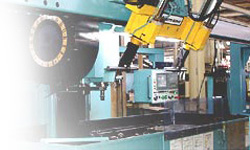
The shaft production line was launched between 1982 and 1984 as a special machining installation for 80 to 132 frame motors. It was a revolutionary flexible manufacturing system (FMS) for its time and featured control, automatic changeover and CAM functions as support for NC program creation.
Since its creation, the production line has had a central role at the Shinshiro Factory with its enhanced capabilities used to process relatively low volume lots of special shafts with different shapes. However, to strengthen its ability to deliver high-mix/low-volume lots and shorten lead times, Mitsubishi Electric wanted to improve line operation methods, many of which relied on manual processes, as well as reduce changeover times.
Rising to the challenge of reducing delivery times for special parts
- There was an information gap between the production system and shop floor equipment:
- Shop floor information was not immediately visible; therefore, the live production situation could not be effectively assessed.
- Manual schedule selection → Processing loss, and less automatic operation during nighttime
- The collection of actual results to formulate plans took time, and it was not possible to respond quickly to changes in production plans or processing defects.
- Loss of NC program input → Changeover time by operator
- Time was needed for the operator to directly input NC programs into machines, which resulted in a loss of productivity. (Number of production models × number of machines = High volume of NC program inputs).
- Work loss due to complicated work instructions and actual process recording
- Manual batch recording of physically inputted slip results.
- Identification of issues
-
- If only the functions of major equipment were improved, then processing accuracy may be enhanced, but there would still be limitations on how productivity could improve. The main issue that need to be resolved was how to perform information processing most efficiently for more than 1,000 types of shaft .
- Key point
-
- The issue was solved by automating the work instruction input, machining order determination (machining schedule), and NC program registration. This was achieved by linking the system with the network.
Key points of improvement activity
1. Including production equipment in real-time transmission of information [Equipment improvement]
(1) Gaining an overview of the entire line and monitoring operations
By adopting a touch panel display (GOT HMI), the entire line and its operational status could be monitored and error history managed, achieving effective visualization of the factory.
(2) Adoption of a control device easily connectable with the host
As well as improving processing accuracy and control performance, products equipped with EZSocket communication middleware could be easily connected to higher-level information systems, providing better exchange of information.
- Machine tools equipped with MELDAS600 series NC devices
- MELSEC-Q series PLCs used to control autoloaders


2. Construction of shaft machining support system including CAM [System construction]
By automating process scheduling and enabling the exchange of information to and from each piece of equipment, changeover times have decreased and the scope of automatic operation has increased.
(1) Automation of schedule selection → Reduced processing loss and increased automatic operation during nighttime
By using a system with the following functions, a scheduler was created that could respond quickly to changes and increase volume.
- By using EZSocket to exchange data with the host production management system, the task became paperless and no longer requires manual intervention.
- EZSocket collects processing completion information from the system and creates a plan reflecting the results.
- Using EZSocket to incorporate actual machining time, an accurate plan that takes advantage of this information is formulated.
- Enable the creation of a plan to increase automatic operation during nighttime.
- Ability to respond to sudden interruptions such as urgent jobs.
(Solution) Installation of equipment for line control (work terminal, dedicated server) and production of system software
(2) Automation of NC program uploading/downloading → Improved changeover capability
- Eliminate line downtime by downloading NC programs to each device via EZSocket according to the schedule.
- Upload of the NC programs to the line controller, so that versions amended during actual machining activities can be stored on the server.
(Solution) Connecting equipment across the entire line, including machine tools, via a LAN line
(3) Simplified work instructions and processing of results → Reduced number of manual tasks
(Solution) Addition of data transmission processing software to the production control system
⇒ Eliminated work instruction slips and slip collection work
System configuration
System features
- 1. Overall start-up control and operation monitoring by touch panel display (GOT HMI)
- 2. Production shop floor scheduling
- 3. Processing information data transfer function
- 4. Work instruction/performance recording function
1. Overall start-up control and operation monitoring by touch panel display (GOT HMI)
This section will introduce the major GOT screen functions of the line.
![]()
●Operation status monitor function [Main screen]
The screen shown here is used to check the operational status of the entire line. A diagram of the line is shown in the center, with the status of each unit and the passage of workpieces displayed in real time.
By interacting with the representation of each unit on the screen, users can inspect the operational status in more detail.
![[Main Screen]](img/img_report04_02.gif)
[Main Screen]
●Operation information confirmation function by unit [In-conveyor unit screen]
This screen is used to check the operational status of each unit.
Users can check detailed information about the workpiece that is being processed in the selected unit as well as individual setting values.
![[In-conveyor unit screen]](img/img_report04_03.gif)
[In-conveyor unit screen]
●I/O check function [I/O check screen]
Operators can check the signal input/output status between each unit and the autoloader by using this screen.
![[I/O check screen]](img/img_report04_04.gif)
[I/O check screen]
●Error history function [Error history screen]
Users can check the log of errors that have occurred when using this screen.
More in-depth information on an error can be viewed by pressing the “Details” button.
![[Error history screen]](img/img_report04_05.gif)
[Error history screen]
●Automatic power off function [Automatic power off time zone setting screen]
This screen is used for setting the time when power to the entire line is shut off.
When all machining instructions are completed within the selected time period, the power supply of the line is automatically turned off as an energy saving measure.
![[Automatic power off time zone setting screen]](img/img_report04_06.gif)
[Automatic power off time zone setting screen]
Click here for product information
2. Production shop floor scheduling
[Before improvement] A production plan was created manually, based on a work instruction slip, (→ Relied on highly skilled operators) and a processing order was determined.

●Optimization of production planning by scheduler
Previously, a high volume of orders marked ‘urgent’ could result in a scenario where scheduling could not be completed before a production run and the order of priority was determined by operators on the shop floor. As a solution to this issue, the following improvements have been realized:
- Schedules can now be created to correspond to the product lead time.
- Machine setup can now be done in a planned way, allowing for more automatic operation during nighttime.
●Matching of production plan and actual processing
It has become possible to track actual machining times, enabling the creation of more accurate schedules.
3. Processing information data transfer function
[Before improvement] Operators manually created NC programs based on a vast volume of workpiece diagram information.

●Improvement of changeover times by automating NC program download
NC programs are stored in the line controller and automatically downloaded to each machine tool.
In addition, results are recorded, so programs stored in the memory of the NC device are automatically uploaded to the line controller.
4. Work instruction/performance recording function
[Before improvement] Paper-based workflow from work instructions to results recording
●Simplification of work instructions
Real-time work instructions transmitted from the production control server via the LAN network. Reduction of slip input time and entry errors.
Elimination of work instruction slips
●Simplification of results recording
Minimization of indirect work by directlsy recording results from terminals on the line.
Elimination of slip collection work
Benefits of the updated system
1.5 times greater productivity!
The automated scheduling and transfer of processing information reduced changeover times and expanded the scope of unmanned operations at nighttime, which led to significantly improved productivity!