Motion module Features (PLCopen ® Motion Control FB Mode)

- Lineup
- Inter-Module Synchronization
- Acceleration/Deceleration Methods
- Synchronous Control
- Touch Probe Function
- Servo System Recorder
- CC-Link IE TSN Safety Communication Function
- Engineering Environment
- GX LogViewer
- Easy Pre-Verification and Troubleshooting
- Security Key Authentication Function
- Quick Start Guide
- Functions List
- Related Link
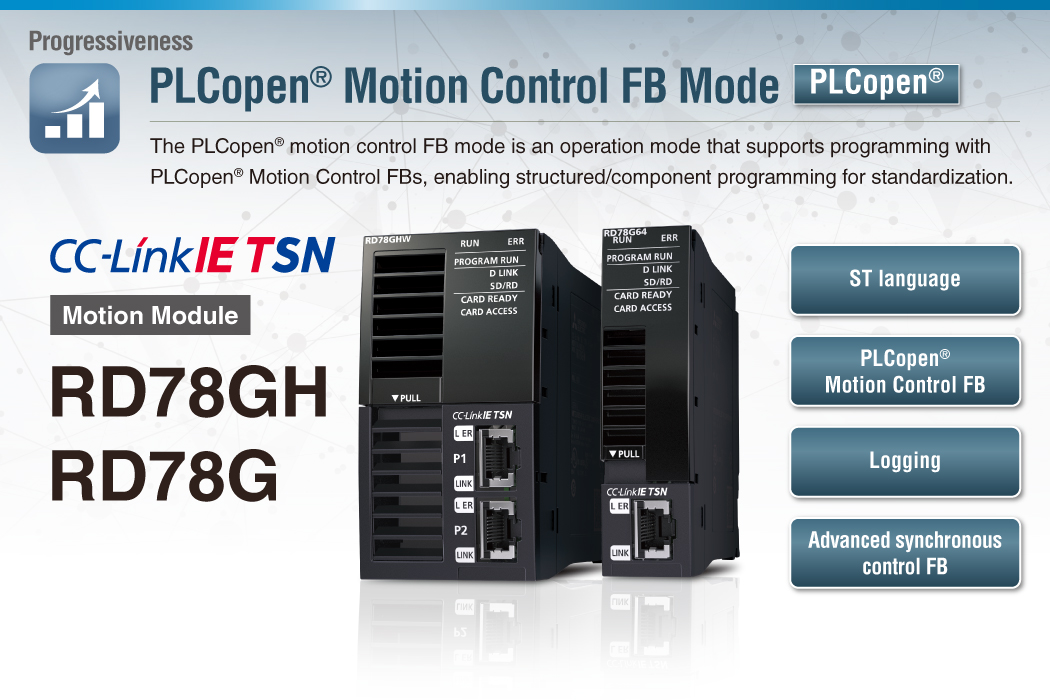

- ● The Motion modules are programmed in ST language. PLC CPUs are in ladder, FBD/LD, and ST language.
- ● The library of PLCopen ® Motion Control FBs, which are compliant with international standards, are available for programming.
- ● Users can analyze the operation status with logging data on GX LogViewer, which improves debug efficiency.
[An example of programming by PLC CPU
(Programming by PLC CPU only) ]
![[An example of programming by PLC CPU (Programming by PLC CPU only) ]](./assets/img/feat_fb-01.png)
A PLC CPU program starts operation of the Motion module, eliminating the need for users to create another program for the Motion module, reducing programming burden.
[An example of programming by each module
(Programming by PLC CPU and Motion modules) ]
![[An example of programming by each module (Programming by PLC CPU and Motion modules) ]](./assets/img/feat_fb-02.png)
Motion modules can execute operations in place of the PLC CPU. This reduces the operation.
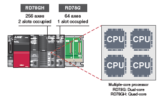
Lineup
RD78GHV
RD78GHW
- Maximum number of control axes:
RD78GHV: 128 axes/module
RD78GHW: 256 axes/module - Minimum operation cycle *1 :
31.25 [μs] - ST language program capacity:
Built-in ROM max. 64 MB + SD memory card
*1. The operation cycle varies by the number of control axes and the models.
RD78G4/RD78G8
RD78G16/RD78G32
RD78G64
- Maximum number of control axes:
RD78G64: 64 axes/module - Minimum operation cycle *1 : 62.5 [μs]
- ST language program capacity:
Built-in ROM max. 16 MB
+ SD memory card
*1. The operation cycle varies by the number of control axes and the models.
Improved Performance
The minimum operation cycle of RD78GH in PLCopen ® motion control FB mode is approximately 4.1 to 6.2 times faster than that of the previous models, and the number of maximum control axes is 4 to 8 times more. The data from the servo amplifiers and input/output signals can be received at high speeds, which reduces the cycle time.
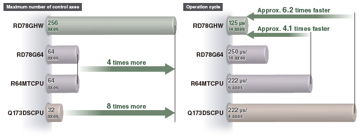
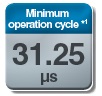


*1. The values are applicable when RD78GH is used.
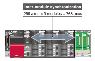
Inter-Module Synchronization
The inter-module synchronization function can synchronize the control timings among multiple Motion modules on the same base unit.
- Machines can be synchronized through this function wheneach machine uses Motion modules.
Acceleration/Deceleration Methods
Three types of acceleration/deceleration methods are available: trapezoidal acceleration/deceleration, jerk acceleration/deceleration, and acceleration/deceleration time fixed.
Trapezoidal acceleration/deceleration
After starting, maximum acceleration is maintained until the target speed is reached.
For example, when a vehicle loaded with a workpiece accelerates suddenly, the workpiece will swing back and forth due to the impact of the sudden acceleration.
To reduce impacts and vibrations in a case such as this, the vehicle must accelerate at a slower rate.
The speed creates a trapezoidal shape.
Jerk acceleration/deceleration
The acceleration changes gradually.
For example, when a vehicle loaded with a workpiece accelerates gradually, the load will not swing back and forth after acceleration.
The jerk is maintained during acceleration.
When the vehicle has almost reached the target speed, the jerk is decelerated. Adjusting jerk in this way achieves smooth acceleration/deceleration while also shortening the time it takes to reach the target speed.
The speed creates a S-curve shape.
Acceleration/deceleration time fixed method
This method executes acceleration/deceleration based on the time specified, regardless of the commanded speed.
- *1. Input acceleration.
- *2. Specify acceleration time.
Synchronous Control
Synchronous control is performed using function blocks that operate as software-based mechanical modules such as gears, shafts, speed change gears, and cams.
- Positioning and synchronous control can be performed together in the same program.
- Synchronous control using a synchronous encoder as an input axis is also possible.
- The output axis is operated based on cam data (operation profile).
Flexibly Combining Synchronous Control FBs
The number and the combination of the synchronous modules are flexibly selected, achieving optimized operation.
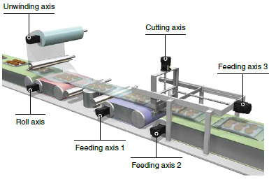
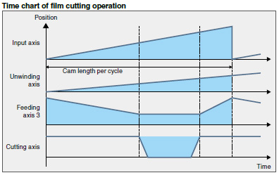
Packing machines
This application synchronizes all the axes,
from the cutting axis through the unwinding axis, with the master axis. Cutting operation is performed with the cutting axis and the feeding axis 3.
Advanced Synchronous Control FB Settings with Graphic-Based Interface
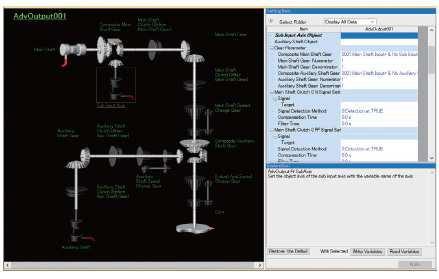
Synchronous control can be easily executed by setting synchronous modules with parameters and starting the advanced synchronous control FB. Synchronous modules such as the auxiliary shafts, gears, clutches, and speed change gears can be set with a graphic-based interface.
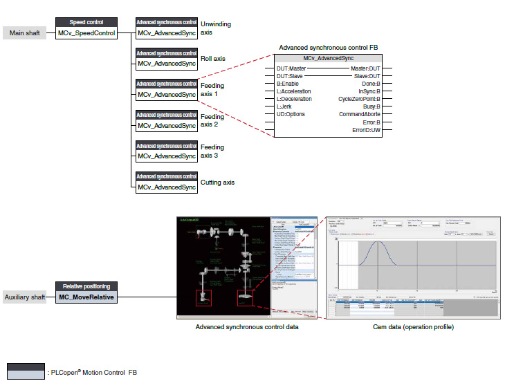
Advanced synchronous control data
Images of enabled synchronous modules are highlighted, allowing easy verification of set data through visualization.
- Input axis data
- Synchronous parameter (output axis)
- Auxiliary shaft data
- Clutch data
- Gear data
- Speed change gear data
- Cam data (operation profile)
- Cam waveform type
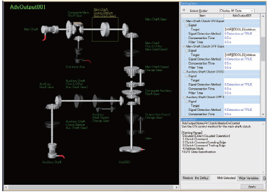
Clutch
The clutch is used to transmit/disengage command pulses from the main/auxiliary shaft input side through turning the clutch ON/OFF, which controls the operation/stop of the output axis.
The clutch can be set to the main shaft clutch and the auxiliary shaft clutch.
| Clutch ON control mode | Clutch OFF control mode |
|---|---|
| Invalid (Direct coupled operation) |
Invalid (OFF control invalid) |
| Clutch command | Clutch command (One-shot operation) |
| Clutch command leading edge | Clutch command leading edge |
| Clutch command trailing edge | Clutch command trailing edge |
| Address mode | Address mode |
| I/O data specification | I/O data specification |
A clutch can be used through the advanced synchronous control FB.3
Advanced synchronous control data
Restarting synchronous control
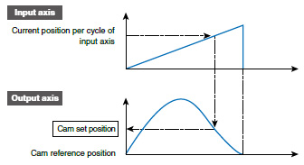
In case that the synchronous positions become misaligned due to an emergency stop, etc, synchronous control can be restarted by using the synchronous control analysis mode.
In the synchronous control analysis mode, the cam set position is updated on the basis of the input axis. The synchronous position can be aligned using the updated cam set position before starting synchronous control.
Synchronous Encoder
The Motion module easily performs synchronous control by setting a synchronous encoder to "Real encoder axis" and creating a program with function blocks.
The number of command pulses can be adjusted using the function block (MC_Gearin) or a parameter.
An incremental synchronous encoder *1 can be connected via a servo amplifier.
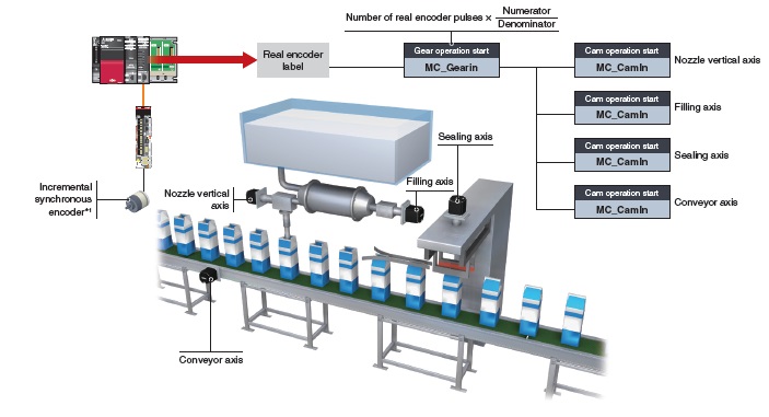
- *1. Supported by MELSERVO-J5 series.
When connecting an absolute position synchronous encoder, use an encoder of HK series servo motors.
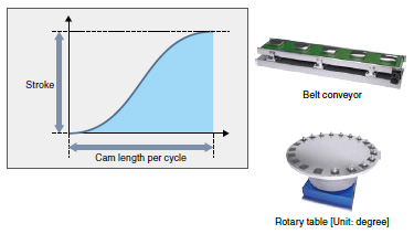
Cam Data (Operation Profile Data)
Create operation profile data *1 (cam data) according to your application. The created cam data is used to control output axis.
*1. "Operation profile data" is a general name for waveform data, which is used for various applications.
■ Cam Operation
The following three cam operations are available: linear operation, two-way operation, and feed operation. Choose one according to your application.
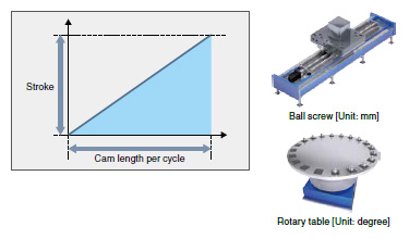
Linear operation
The cam pattern is a linear line.
This pattern is used for a ball screw and a rotary table.
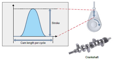
Two-way operation
The beginning and the end of the cam pattern are the same.
Mechanical cams fall into this category.
Feed operation
The beginning and the end of the cam pattern differ.
This pattern is used for fixed-amount feed operations and intermittent operations.
Set the end point for the feed operation to a position of your choice.
Touch Probe Function
This function latches data responding to a trigger signal input to a servo amplifier.
The compensation amount is calculated based on the latched data, and the error is compensated using a compensation axis.
A high-accuracy touch probe at 1 μs is possible.
Servo System Recorder
The Motion module automatically collects data of all servo amplifiers when an error occurs. The collected data, such as the command and the feedback values, greatly helps you analyze the error cause.
- Automatic collection of data, such as position, speed, and torque data, without programming.
- Data collection of all axes, which helps you locate the error cause even when the error is caused by the other axes without an error.
- The co-recording function collects data even when an error occurs in other recording devices.
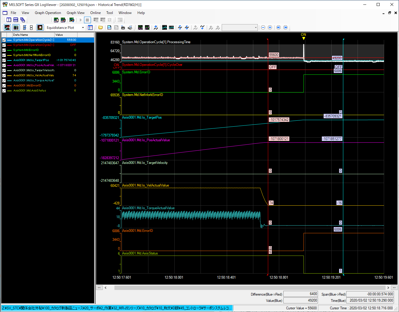
GX LogViewer
The collected data can be checked on GX LogViewer.
The operation status before and after an error is displayed in waveform, which allows you to analyze more operation details and helps you locate the error cause.
[Features]
- Displays the collected data and events graphically.
- Enables users to adjust a graph easily by automatic adjustment function and drag operation.
CC-Link IE TSN Safety Communication Function
CC-Link IE TSN enables control of safety and non-safety communications realizing a flexible system whereby safety communications can be easily incorporated into the main control network.
In the following system which integrates safety and non-safety communications, the safety CPU checks the safety signals received via the safety remote I/O module and outputs the safety signals (STO, etc.) to the servo amplifiers. Outputting safety signals via the network eliminates the need for wiring of safety signals to a safety controller and a servo amplifier.
*1. Supported by MELSERVO-J5 series.
For servo amplifiers that support the safety communication function, refer to "Safety Sub-Functions" .
Engineering Environment
MELSOFT GX Works3 covers various aspects of development processes - parameter settings, servo adjustments, and debugging of Motion modules as well as sequence program creation. This software offers an engineering environment that provides comfortable design environment.
MELSOFT GX Works3
Various features are integrated into GX Works3, which allows users not only to easily create projects but also maintain consistency through the entire development processes.

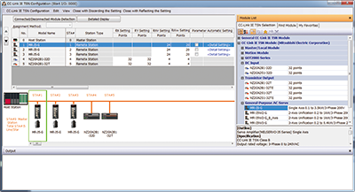
■ Network Configuration Settings
[Network configuration settings]
- Intuitive network settings with drag-and-drop operations and a graphical screen view
[Automatic detection]
- By clicking the [Connected/Disconnected Module Detection] button, the connection status of device stations is automatically detected and the CC-Link IE TSN configuration screen is generated.
■ Easy Programming Through Structured Text Language
- Structured text programs are composed of function blocks, increasing program readability.
- Modularization of the programs increases their reusability.
- The consistent, common operability on a single engineering tool improves usability further.
- A wide selection of programming elements in the MELSOFT Library contributes to reducing programming time.
- The program is created by dragging & dropping programming elements, which simplifies the programming process.
- A startup time is reduced using the simulator of MELSOFT GX Works3 that can debug a program without an actual machine.
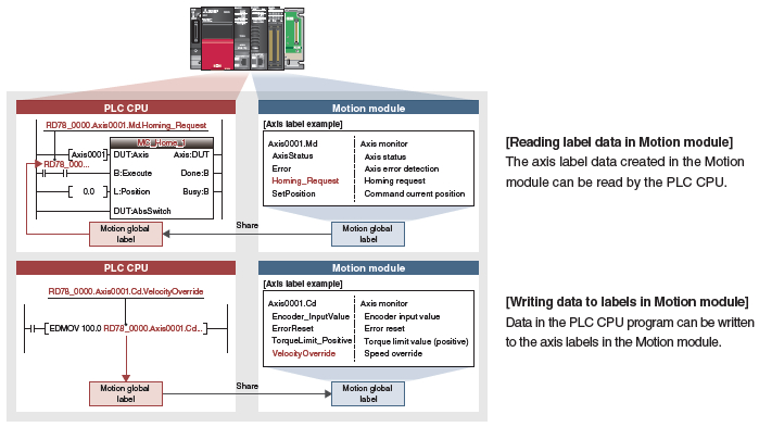
■ Programming Using Labels
- The control axes of the Motion modules and I/O signals are defined as label variables, which enables easy reuse of programs and helps to improve programming efficiency.
- The global labels created in the Motion module project can be used in PLC CPUs.
GX LogViewer
The graph data of both PLC CPU modules and Motion modules can be checked on GX LogViewer. This tool helps you efficiently analyze data from two different modules. The following two functions are provided for logging: data logging function (offline) and real-time monitor.
■ Data Logging Function
The function performs data logging by a specified time interval based on the logging setting (trigger condition, data collection) written to the motion module from the engineering tool. The results are saved as a data logging file.
Up to 10 data settings can be simultaneously logged for the motion module.
The operation status before and after an error is displayed in waveform, which allows you to analyze more operation details and helps you locate the error cause.
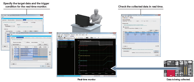
■ Real-time monitor
Up to 32 collected motion module data can be displayed in real time.
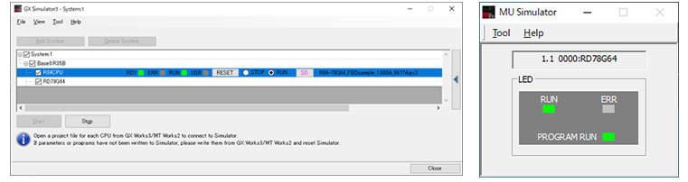
Easy Pre-Verification and Troubleshooting
The system simulator enables the Motion module and PLC CPU programs to be simulated interactively.
A program operation can be checked without an actual machine during debugging process, which shortens the startup time.
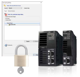
Security Key Authentication Function
The security key authentication prevents programs from being opened on personal computers where the security key has not been registered. Furthermore, because programs can be executed only by Motion modules with the security key registered, the integrity of customer technologies and other intellectual property is not compromised.
Quick Start Guide
Functions List
| Motion Module | |||||||
|---|---|---|---|---|---|---|---|
| RD78GHW | RD78GHV | RD78G64 | RD78G32 | RD78G16 | RD78G8 | RD78G4 | |
| Maximum number of control axes | 256 | 128 | 64 | 32 | 16 | 8 | 4 |
| Minimum operation cycle [μs] *1 | 31.25 | 62.5 | |||||
| Servo amplifier connection method | CC-Link IE TSN (Communications speed: 1 Gbps/100 Mbps) | ||||||
| Connectable servo amplifier | MR-J5-G, MR-J5W-G, MR-J5D-G4 More details MR-JET-G More details |
||||||
| Maximum distance between stations [m(ft.)] |
100(328.08) | ||||||
| Control modes | Position control, Speed control, Torque control, Synchronous control, Cam control | ||||||
| Positioning control | Position control, Linear interpolation (Up to 4 axes), Circular interpolation (2 axes) | ||||||
| Acceleration/deceleration process | Trapezoidal acceleration/deceleration, Jerk acceleration/deceleration, Acceleration/deceleration time fixed method |
||||||
| Programming language | PLC CPU: Sequence program, FBD/LD, ST Motion module: ST |
||||||
| Home position return | Driver home position return *2 | ||||||
| Manual control | JOG operation | ||||||
| Auxiliary functions | Forced stop, Hardware stroke limit, Software stroke limit, Absolute position system, |
||||||
| Common functions | Touch probe, Axis emulate, Event history, Monitoring of servo data, Servo system recorder, Inter-module synchronization |
||||||
| Engineering environment | MELSOFT GX Works3 | ||||||
| Number of I/O occupying points | 32 points + 16 points (empty slot) | 32 | |||||
| 5VDC internal current consumption [A] |
2.33 | 1.93 | |||||
| Mass [kg] | 0.44 | 0.26 | |||||
- *1. The minimum operation cycle varies depending on the number of control axes and the model.
- *2. The home position return method set in a driver (a servo amplifier) is used.
- *3. Supported by MELSERVO-J5 series.