Motion module Features (Simple Motion Mode)

- Lineup
- Positioning Control
- Advanced Synchronous Control
- Continuous Operation to Torque Control
- Auxiliary Functions
- CC-Link IE TSN Safety Communication Function
- Optional Data Monitor
- Driver Communication
- Engineering Environment
- Functions List
- Related Link
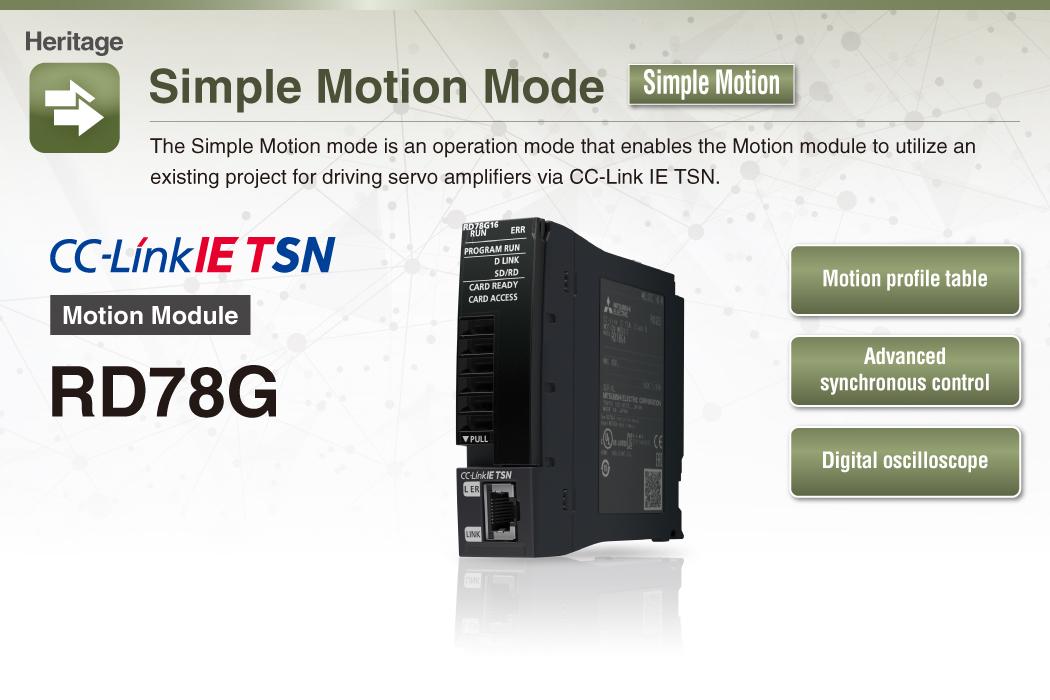

- ● Positioning control can be easily performed with motion profile tables. Synchronous control can be executed only with parameter settings.
- ● Remote devices are connected via CC-Link IE TSN and programmed from PLC CPUs.
- ● Data that is synchronized with the motion operation cycle can be collected with the digital oscilloscope. The collected data is displayed in waveforms for operation verification.
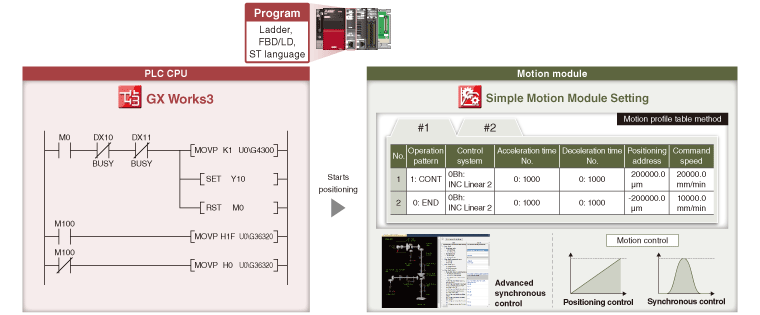
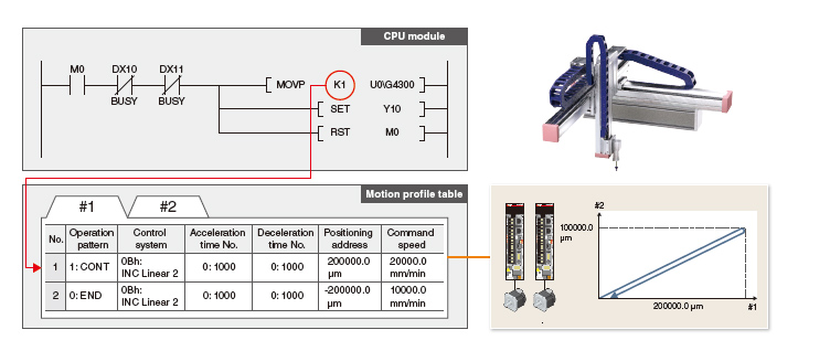
[An example of programming by a PLC CPU]
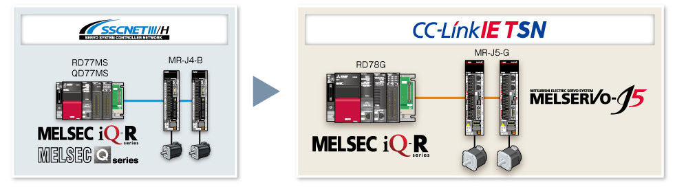
Utilization of Existing Programs
The existing MELSEC iQ-R/MELSEC-Q series devices and programs are reusable in a new system of RD78G Motion module that supports the Simple Motion mode.
Lineup
RD78G4
RD78G8
RD78G16
- Maximum number of control axes: 16 axes/module (RD78G16)
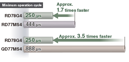
- Minimum operation cycle *1 : 250 [μs]
- *1. The operation cycle varies by the number of control axes and the models.
Improved Performance
The minimum operation cycle of RD78G in Simple Motion mode is approximately 1.7 to 3.5 times faster than that of the previous models. The data from the servo amplifiers and input/output signals can be received at high speeds, which reduces the cycle time.
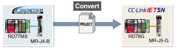
Reuse of Existing Projects
The existing projects of a Simple Motion module can be reused. This enables reduction in program development time.
RD77MS→RD78G
Select [Change Module] in the navigation menu of GX Works3 to convert the Simple Motion module project to a Motion module project.
After the conversion, set the network parameters, servo amplifier parameters, and other parameters.
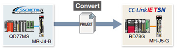
QD77MS→RD78G
Select [Import Simple Motion Module Data] in the navigation menu of GX Works3 to import the parameters of QD77MS.
After the import, set the network parameters, servo amplifier parameters, and other parameters.
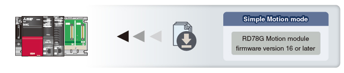
Firmware of RD78G Motion Module
The Simple Motion mode is supported by RD78G with firmware version 16 or later.
To obtain the firmware update files, contact your local sales office.
Positioning Control
Positioning control is easily executed using a motion profile table.
- To meet various application needs, the Motion module offers various types of positioning control, such as linear interpolation, 2-axis circular interpolation, fixedpitch feed, and continuous path control.
- Positioning control can be executed easily by setting the positioning address, the speed, and other setting items in a sequence program.
- Powerful sub-functions, such as M-code output, skip, speed change, and target position change functions, are available.
Programming
The Motion module easily executes positioning operation with the instruction in a sequence program that starts a positioning data of the motion profile table.
Advanced Synchronous Control
Synchronous control can be achieved using software instead of controlling mechanically with gear, shaft, clutch, speed change gear or cam, etc.
- Synchronous control can be flexibly started/ended for each axis, enabling the synchronous control axis and positioning control axis to be used within the same program.
- Command generation axis, servo input axis, or synchronous encoder axis *1 can be set as the input axis.
- The output axis is operated with a cam. The following three operations can be performed with the cam functions: linear operation, two-way operation, and feed operation.
- An incremental synchronous encoder *2 can be connected via servo amplifier.
- *1. Supported by MELSERVO-J5 series.
- *2. When connecting an absolute position synchronous encoder, use an encoder of HK series servo motors.
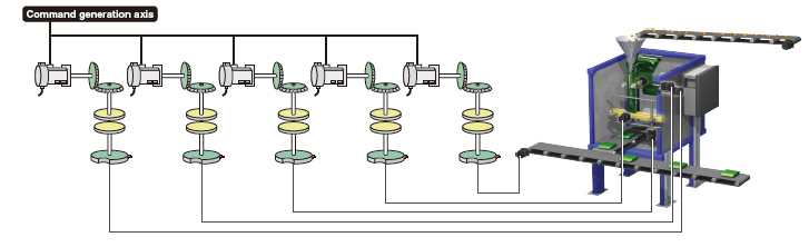
[Command generation axis]
Command generation axis is the axis that performs only the command generation.
It is controlled independently of other axes connected to servo amplifiers. (not counted as a control axis)
Parameter Settings
Synchronous control is executed by setting parameters of the input axis, output axis, gear, and clutch for synchronous control and turning on the synchronous control start signal.
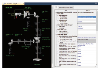
Cam Data (Operation Profile Data)
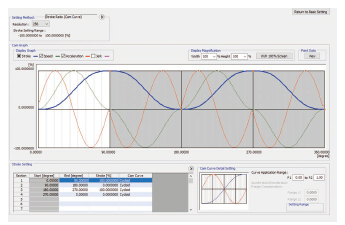
The cam graph can be flexibly and easily created through drag & drop. The waveform is changed according to the pointer's movement.
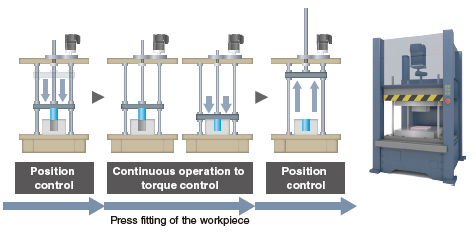
Continuous Operation to Torque Control
The axes are controlled to run at the constant torque by following the torque command while the current position is being trucked.
Switching from position control to torque control continuously can be performed without stopping the servo motor.
Auxiliary Functions
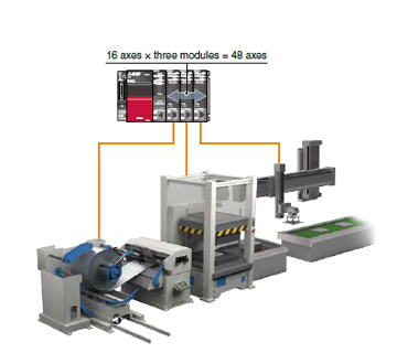
Inter-Module Synchronization
The inter-module synchronization function can synchronize the control timings among multiple Motion modules on the same base unit.
Machines can be synchronized through this function when each machine uses Motion modules.
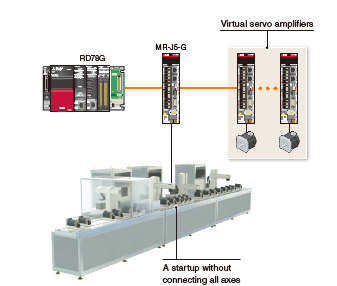
Virtual Servo Amplifier
The virtual servo amplifier function enables operations of a virtual servo amplifier as if an actual unit is connected. When the virtual servo amplifier is set as a servo input axis of synchronous control, the Motion module executes synchronous control with virtually generated input commands. In addition, this function is used to simulate an axis without an actual connection.
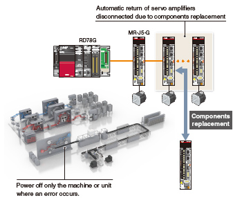
Automatic Return
When device stations are back to normal status after disconnected due to a data link error, this function automatically returns the disconnected stations to the network and restarts data link.
Parts can be replaced by turning off only the machine where an error occurred. Powering off the whole system is not required.
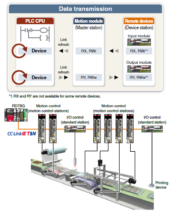
Read/Write Operation of Standard Stations
- The PLC CPU sends/receives link devices to/from standard stations (device stations other than the motion control stations) through a Motion module.
- One-to-one communication is possible between the master and device stations.
- The PLC CPU can be programmed using the signals of the device stations.
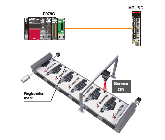
Mark Detection
This function latches data responding to a trigger signal input to a servo amplifier.
The compensation amount is calculated based on the latched data, and the error is compensated using a compensation axis.
A high-accuracy mark detection at 1 μs is possible.
CC-Link IE TSN Safety Communication Function
CC-Link IE TSN enables control of safety and non-safety communications realizing a flexible system whereby safety communications can be easily incorporated into the main control network.
In the following system which integrates safety and non-safety communications, the safety CPU checks the safety signals received via the safety remote I/O module and outputs the safety signals (STO, etc.) to the servo amplifiers. Outputting safety signals via the network eliminates the need for wiring of safety signals to a safety controller and a servo amplifier.
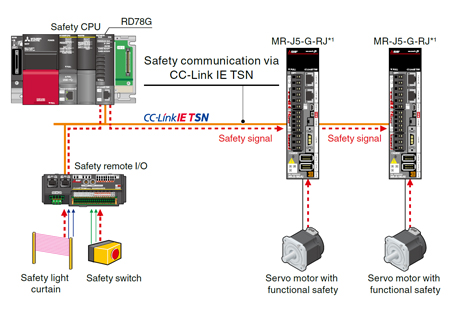
- *1. Supported by MELSERVO-J5 series.
For servo amplifiers that support the safety communication function, refer to "Safety Sub-Functions" .
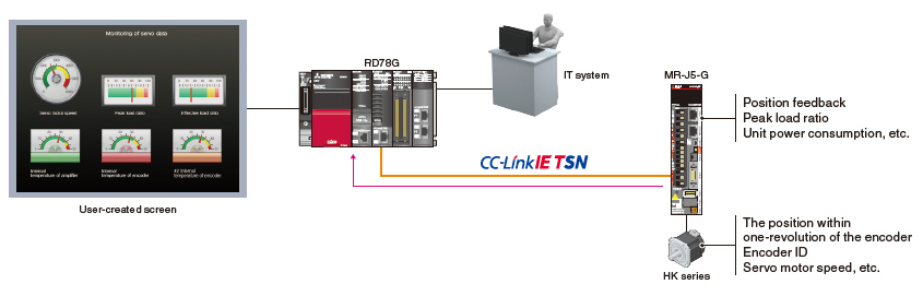
Optional Data Monitor
Servo operation is monitored with extensive servo data acquired via CC-Link IE TSN. The acquired data can be transferred to IT system or transferred and displayed on any user-created GOT screen in the network. The target data for monitoring can be flexibly changed during operation.
Driver Communication *1
By using the driver communication function of the servo amplifier, the master axis is controlled with the Motion module, while the following axes are controlled by data communication between servo amplifiers (driver communication) without using the Motion module.
The Motion module can drive multiple axes by controlling only the master axis.
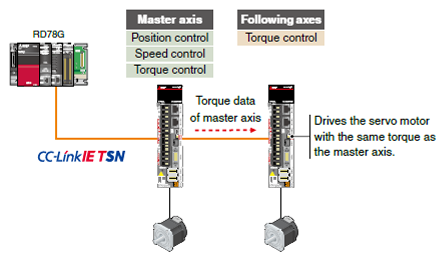
- *1. Supported by MELSERVO-J5 series.
Engineering Environment
MELSOFT GX Works3 covers various aspects of development processes - parameter settings, servo adjustments, and debugging of Motion modules as well as sequence program creation. This software offers an engineering environment that provides comfortable design environment.
MELSOFT GX Works3
Various features are integrated into GX Works3, which allows users not only to easily create projects but also maintain consistency through the entire development processes.

System Design
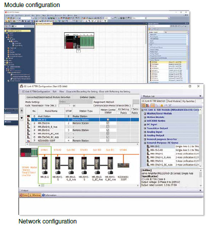
- Module configuration
- Network configuration
- Data settings for servo amplifiers
- Settings for remote I/O
- Parameter conversion function
Programming (Positioning)
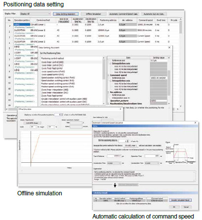
- Programming with Ladder, SFC, FBD/LD
- Positioning data settings
- Offline simulation, automatic calculation of command speed
Programming (Advanced Synchronous Control)
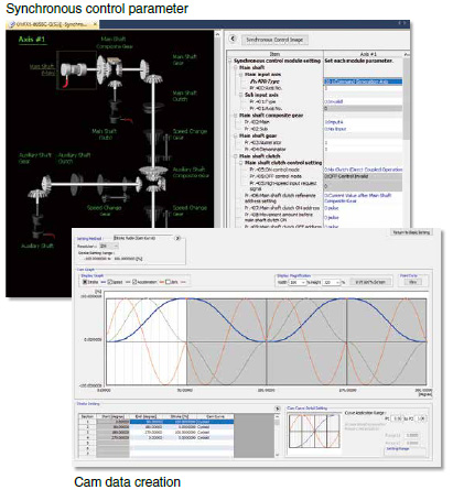
- Synchronous control parameter
- Cam data creation, cam data list
Debug/Maintenance
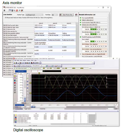
- Event history
- Current value history, start history, axis monitor
- Servo monitor
- Digital oscilloscope
Functions List
| Motion Module | ||||
|---|---|---|---|---|
| RD78G16 | RD78G8 | RD78G4 | ||
| Maximum number of control axes | 16 | 8 | 4 | |
| Minimum operation cycle [μs] *1 | 250 | |||
| Servo amplifier connection method | CC-Link IE TSN (Communications speed: 1 Gbps/100 Mbps) | |||
| Connectable servo amplifier | MR-J5-G, MR-J5W-G, MR-J5D-G4 More details MR-JET-G More details |
|||
| Maximum distance between stations [m(ft.)] | 100 (328.08) | |||
| Control modes | Position control, Speed control, Torque control, Synchronous control, Cam control | |||
| Positioning control | Position control, Linear interpolation (Up to 4 axes), Circular interpolation (2 axes), Helical interpolation |
|||
| Acceleration/deceleration process | Trapezoidal acceleration/deceleration, S-curve acceleration/deceleration | |||
| Positioning control method | Motion profile table | |||
| Home position return | Driver home position return *2 | |||
| Manual control | JOG operation, Manual pulse generator operation, Inching operation | |||
| Auxiliary functions | Forced stop, Hardware stroke limit, Software stroke limit, Absolute position system, Digital oscilloscope function, Acceleration/deceleration time change, Inter-Module Synchronization, Target position change, Torque limit value change, Speed change, Override, CC-Link IE TSN safety communication function *3 |
|||
| Common functions | Driver Communication, Mark detection, Virtual servo amplifier, Event history, Optional data monitor | |||
| Engineering environment | MELSOFT GX Works3 | |||
| Number of I/O occupying points | 32 | |||
| 5VDC internal current consumption [A] | 1.93 | |||
| Mass [kg] | 0.26 | |||
- *1. The minimum operation cycle varies depending on the number of control axes and the model.
- *2. The home position return method set in a driver (a servo amplifier) is used.
- *3. Supported by MELSERVO-J5 series.