Motion controller Features

Q173DSCPU/Q172DSCPU
- Multiple CPU Control by PLC CPU and Motion CPU
- High Response Control
- Control Flow
- Reduced Wiring, Space Saving
- High-speed Synchronous Network SSCNETIII/H
- Advanced Synchronous Control
- Safety Communication via SSCNETIII/H
- Engineering Environment MELSOFT MT Works2
- Functions List
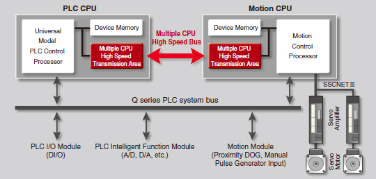
Multiple CPU Control by PLC CPU and Motion CPU
CPU loads are distributed by sharing tasks between the Motion controller and the Programmable controller. Complex servo controls are executed by the Motion controllers, while machine and information control is managed by the Programmable controllers. By selecting the Motion CPU and PLC CPU according to the application, a flexible system is configured. The program of Motion CPU is described with the Motion SFC program.
[Multiple CPU High Speed Bus]
-
Equipped with a Multiple CPU high speed bus reserved specifically for CPUto-CPU communication.
With this reserved Multiple CPU high speed bus, data transfer of 0.88ms period is possible for up to 14k words. -
The Multiple CPU high speed transmission cycle is synchronized with the motion control cycle thus optimizing the control system.
[Sequence program]
-
Ladder description is suitable for scan process
(Importance focused on condition control)

-
Sequence control
(Compatible with multiple I/O points, multiple operations) - System stop processing at error detection
[Motion SFC program]
-
Motion SFC description is suitable for event processes
(Importance focused on sequential control, pursuit of event responsiveness)
- Servo high-speed response (Start)
- Positioning address, speed data operation, speed change
- High functionality with multitasking and branching
[Motion Dedicated PLC Instruction]
■Introducing easy-to-use Motion dedicated PLC instructions.
[PLC program interrupt for Multiple CPUs synchronization]
■Using the new PLC interrupt function synchronized with the motion operation cycle (0.88ms),
it is possible to achieve real time processing of the ladder program.Application Example
-
1) A motor real time value can be compared against a specific point and if this point is overrun, the PLC can turn on an output signal.
(Variation of comparison processing does not have an influence on the scan time of the ladder which is processed within 0.88ms.) - 2) Multiple Motion CPUs can be started simultaneously.
-
Ladder description is suitable for scan process
High Response Control
The Motion operation cycle of 0.22 ms/4 axes is achieved to meet customer needs for a shorter tact time.
Even at an operation cycle of 0.44 ms, up to 10 axes are controlled without losing high response.
[Perfect for smooth curve control]
The command data from the Motion controller is transmitted to the servo amplifier every 0.22 ms.
Motion Controller with Servo amplifier (MR-J4-B) and servo motor (HG-KR motor: 4,194,304pulse/rev) achieves the shorter operation cycle and smooth motion.
Control Flow
Reduced Wiring, Space Saving
The number of wires and parts is drastically reduced when the Motion controller is used with 2-axis servo amplifier or 3-axis servo amplifier of MR-J4 series. When the Motion controller is used with MR-J4W3-B servo amplifier (3-axis type), the installation space is reduced by approximately 30%.
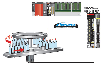
High-speed Synchronous Network SSCNETIII/H
-
Communications speed is increased to 150 Mbps full duplex (equivalent to 300 Mbps half duplex), three times faster than the conventional speed.
System response is dramatically improved. - Smooth control of a machine is possible using high-speed serial communications with a cycle time of 0.222 ms.
- Synchronous communications are achieved with SSCNETIII/H, offering technical advantages for machines that require deterministic control.
- Long distance wiring is possible up to 3200 m (10498.69 ft.) per system (maximum of 100 m (328.08 ft.) between stations x control axes up to 32 axes), suitable for large-scale systems.
-
SSCNETIII/H compatible and SSCNETIII compatible servo amplifiers can be used together.
(The communications speed when SSCNETIII compatible products are used together in the same system: 150 Mbps full duplex)
(Note): SSCNET (Servo System Controller Network)
Advanced Synchronous Control
The advanced synchronous control can be achieved using software instead of controlling mechanically with physical gears, shafts, clutches, speed change gears or cams etc.
Additionally, a cam is easily created with the cam auto-generation function.The synchronous control can be started/ended on axis-by-axis basis.
Axes in synchronous and positioning controls can be used together in one program. Speed-torque control can be performed simultaneously with the synchronous control.
[Control flow]
[Synchronous control parameters]
- The synchronous control is easily executed just by setting parameters.
- The movement amount of the main shaft can be transmitted to output axes via the clutch.
- "Command generation axis" is not considered as a control axis; therefore the output axes can be set using all of the available control axes.
Safety Communication via SSCNETIII/H
A combination of the MR-J4-B-RJ servo amplifier and the MR-D30 functional safety unit realizes IEC 61800-5-2 functions (STO, SS1, SSM, SBC, and SLS). The safety sub-function can be easily started with the parameter settings of MR-D30. When the MR-D30 functional safety unit is used, creating the sequence program for functional safety is not required.
The servo amplifier with software version B3 or later supports the safety sub-function.
[Safety system example using MR-J4-B-RJ and MR-D30]
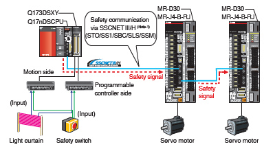
The wiring for power shutoff (STO) between the outputs on controller side and the servo amplifier is no longer needed.
Safely-limited speed (SLS) is available without an external pulse generator.
(Note-1): The safety communication via SSCNETIII/H complies with IEC 61784-3:2010.
Engineering Environment MELSOFT MT Works2
A robust and easy-to-use programming environment for advanced Motion control.
[System Design]
- You can easily set servo amplifiers and various modules with a graphical system setting screen.
- The complicated electric gear settings can be completed just by specifying the mechanical configuration (reduction ratio, ball screw pitch, etc.).
SSCNET structure
Electronic gear setting
[Programming]
- User-friendly functions for program development.
- Easily divert the existing SFC program from the original project to the new project just by drag&drop.
Servo program list
[Setup and Adjustment]
- Simulator function executes the debugging of the Motion SFC program and the advanced synchronous control on desktop without using an actual machine.
- Operation check and troubleshooting are powerfully supported with data collection and wave displays which are synchronized to the Motion operation cycle.
Simulator
Digital oscilloscope
Functions List
| Motion controller | ||
|---|---|---|
| Q173DSCPU | Q172DSCPU | |
| Servo amplifier interface | SSCNETIII/H | |
| 2 lines | 1 line | |
| Connectable servo amplifier |
MR-J5-B, MR-J5W-B
More details
MR-J4-B, MR-J4W-B More details MR-JE-B More details |
|
| Number of control axes | Up to 32 axes | Up to 16 axes |
| Operation cycle[ms] | From 0.22ms | |
| Engineering Environment | MELSOFT MT Works2, MR Configurator2 (Note-1) | |
| Programming method | Motion SFC | |
| Control modes |
Position control, Speed control, Torque control, Tightening & press-fit control,
Synchronous control, Cam control, Advanced synchronous control |
|
| Positioning control |
PLinear interpolationm, Circular interpolation, Continuous trajectory control, Helical interpolation,
Position follow-up control,
Speed control with fixed position stop, High-speed oscillation control, Speed/position switching control |
|
| Acceleration/deceleration process | Trapezoidal acceleration/deceleration, S-curve acceleration/deceleration, Advanced S-curve acceleration/deceleration | |
| Manual control | JOG operation, Manual pulse generator, JOG operation simultaneous start | |
| Functions that change control details | Current value change, Target position change, Torque limit value change, Speed change | |
| Home position return method |
Proximity dog method 1, Proximity dog method 2, Scale home position signal detection method, Count method 1,
Count method 2, Count method 3, Data set method 1, Data set method 2, Dog cradle method, Stopper method 1, Stopper method 2, Limit switch combined method, Dogless home position signal reference method |
|
| Auxiliary functions |
Forced stop method, Hardware stroke limit method, Software stroke limit method, Absolute position system,
Amplifier-less operation method, Unlimited length feed method, Optional data monitor method, Mark detection method, ROM operation function, M-code output method, Error history, Digital oscilloscope method, Safety sub-function, Vision system connection function, Software Security Key Function, High-speed reading function, Limit switch output method, Cam auto-generation method |
|
(Note-1): MELSOFT MR Configurator2 is included in MELSOFT MT Works2.